
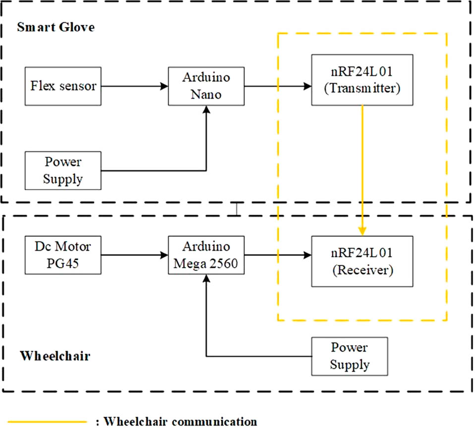
Figure 1
Block diagram of proposed system.
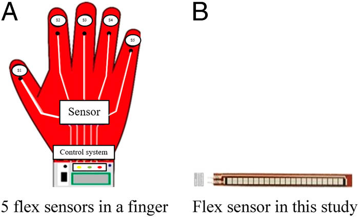
Figure 2
Flex sensors installed in this study: (a) and (b).
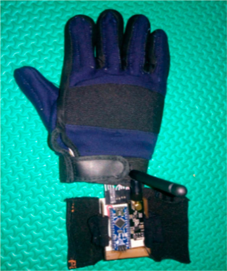
Figure 3
Smart glove hardware.
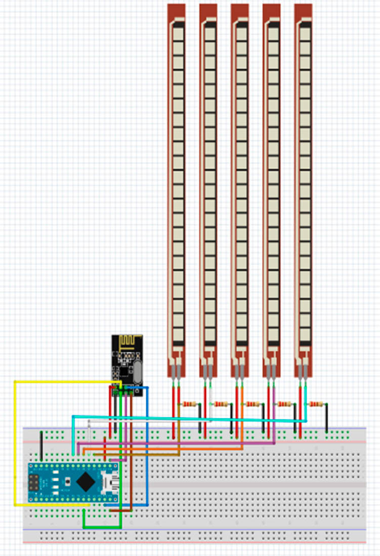
Figure 4
Electrical wiring in the smart glove.
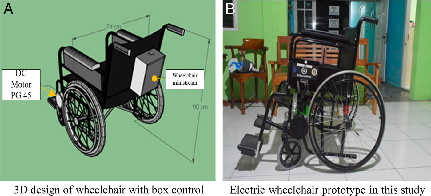
Figure 5
Electric wheelchair Hardware: (a) 3D design, and (b) prototype.
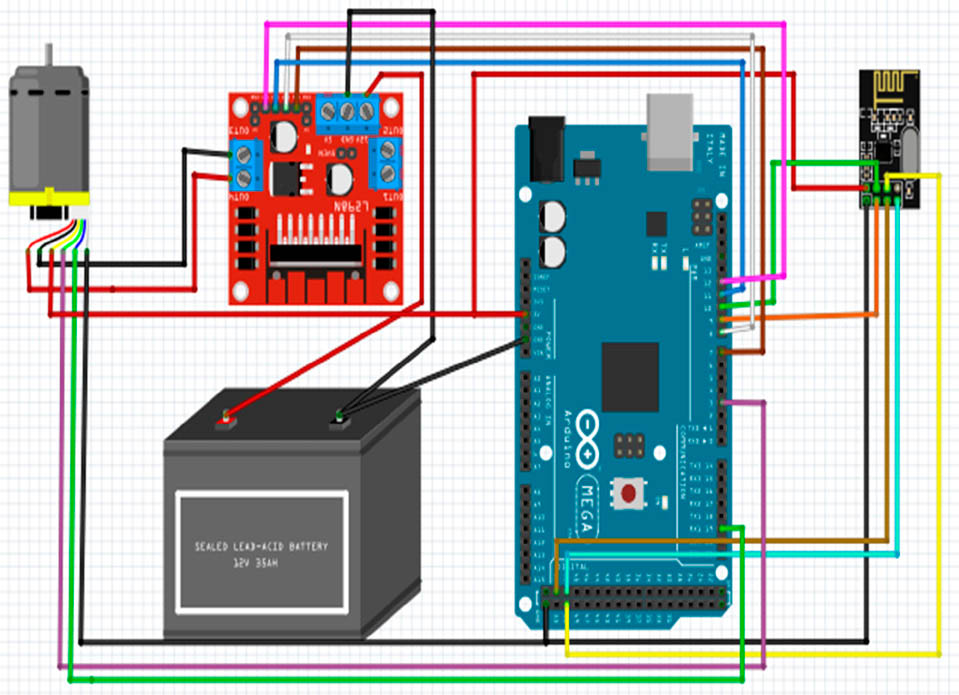
Figure 6
Electrical wiring in an electric wheelchair.
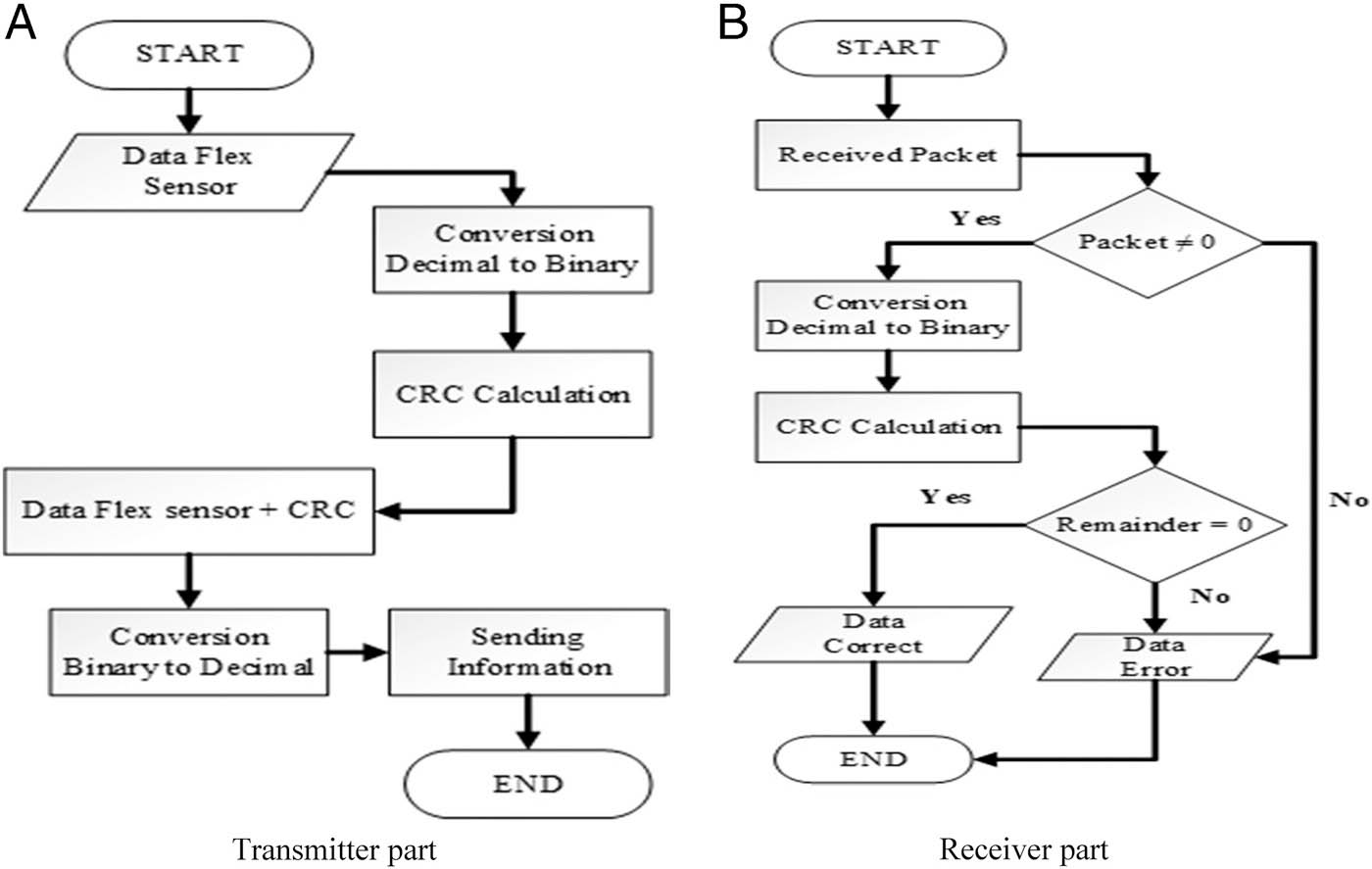
Figure 7
CRC flow chart on: (a) the transmitter part and (b) the receiver part.
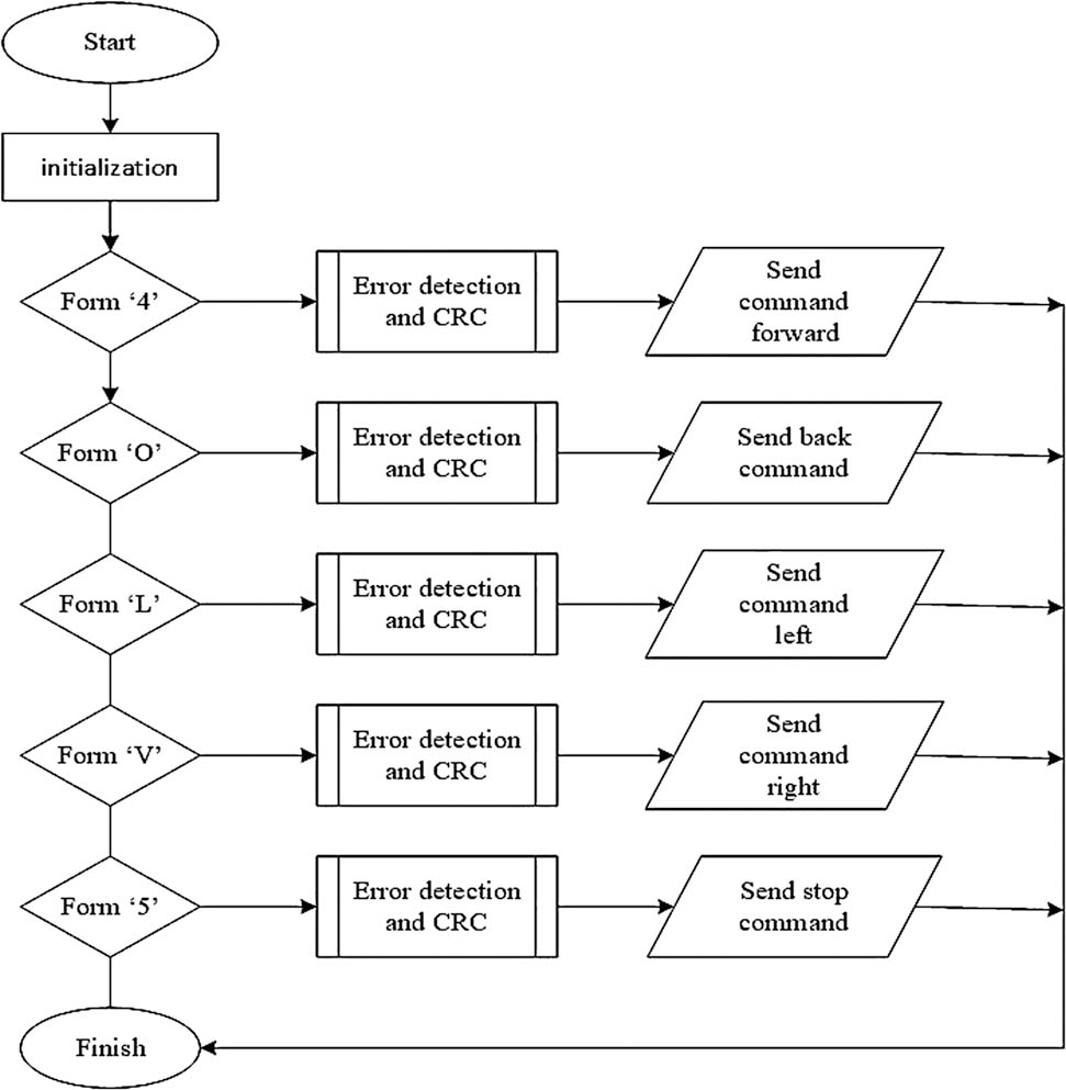
Figure 8
All instruction of smart glove system as electric wheelchair controller.
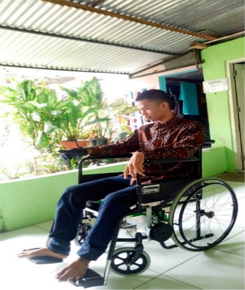
Figure 9
Hardware Testing.
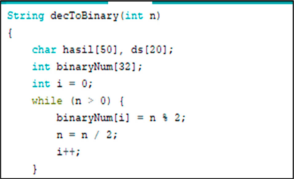
Figure 10
Decimal to binary conversion formula.
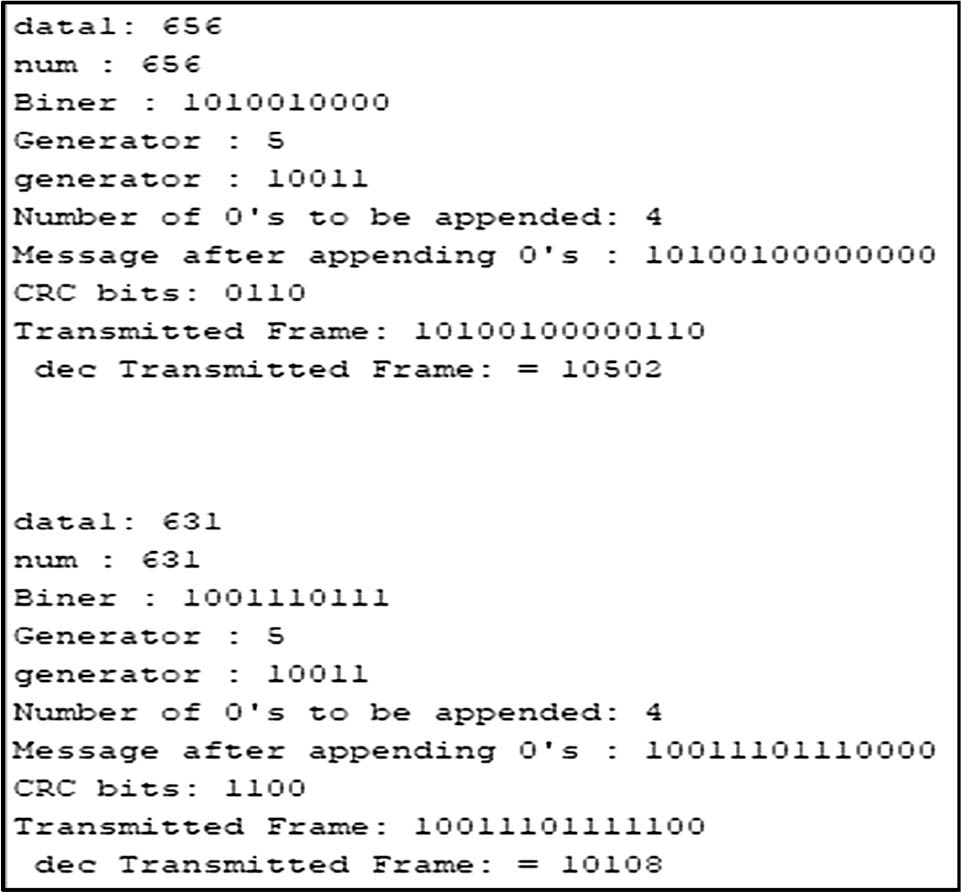
Figure 11
CRC Calculation results for the transmitter part.
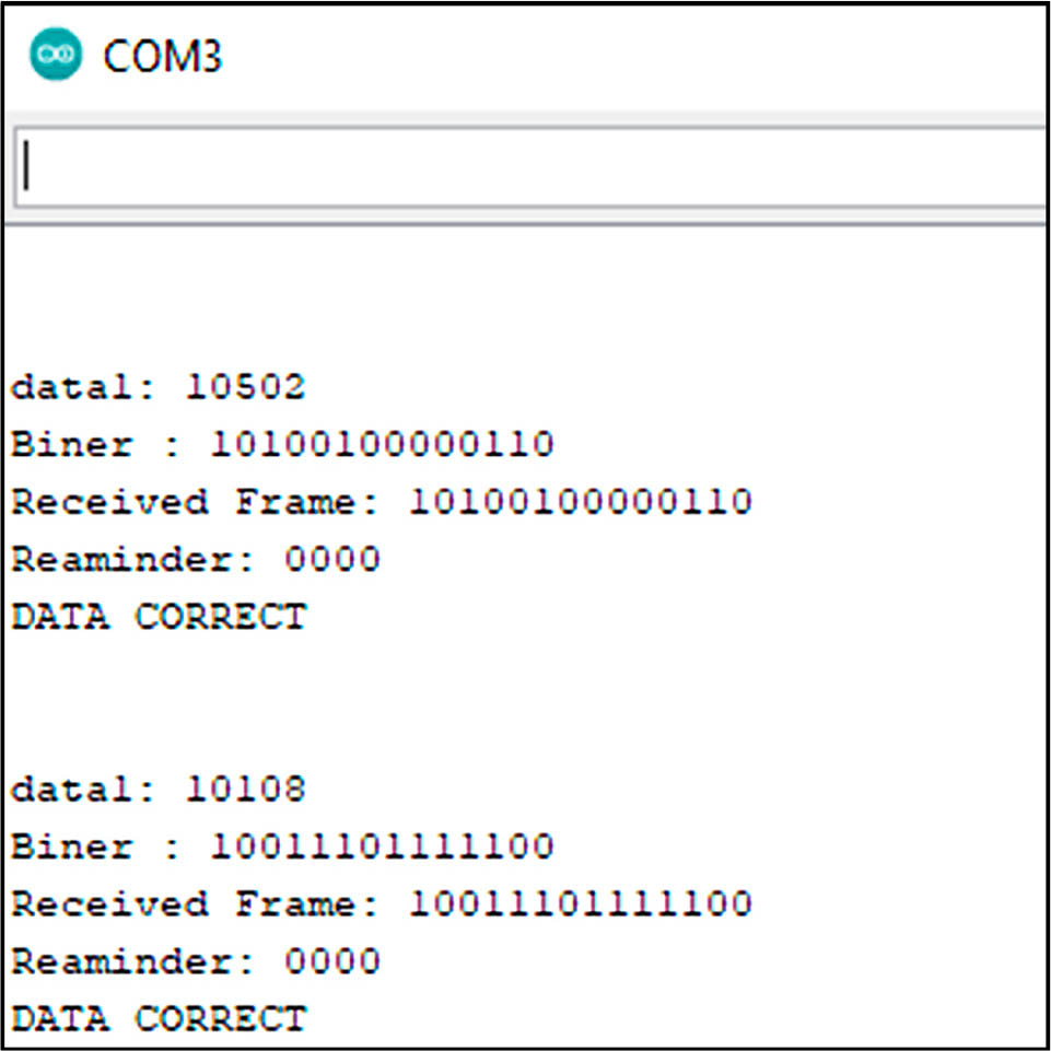
Figure 12
CRC results on the receiver.
Table 1
Error detection testing on transmitter data and receiver data.
| No | Transmitter | Receiver | ||||||
|---|---|---|---|---|---|---|---|---|
| conversion Dec to Binary | ||||||||
| Data Flex Sensor | Binary | CRC | Transmit Frame | Receiver Frame | Remainder | Data Flex Sensor | Status | |
| 1 | 364 | 101101100 | 0101 | 1011011000101 | 0 | 0 | 0 | Error |
| 2 | 354 | 101100010 | 0100 | 1011000100100 | 1011000100100 | 0 | 354 | Success |
| 3 | 359 | 101100111 | 1011 | 1011001111011 | 1011001111011 | 0 | 359 | Success |
| 4 | 361 | 101101001 | 1010 | 1011010011010 | 0 | 0 | 0 | Error |
| 5 | 364 | 101101100 | 0101 | 1011011000101 | 1011011000101 | 0 | 364 | Success |
| 6 | 362 | 101101010 | 1111 | 1011010101111 | 1011010101111 | 0 | 362 | Success |
| 7 | 363 | 101101011 | 1100 | 1011010111100 | 1011010111100 | 0 | 363 | Success |
| 8 | 364 | 101101100 | 101 | 1011011000101 | 1011011000101 | 0 | 364 | Success |
| 9 | 360 | 101101000 | 1001 | 1011010001001 | 1011010001001 | 0 | 360 | Success |
| 10 | 353 | 101100001 | 0001 | 1011000010001 | 0 | 0 | 0 | Error |
| 11 | 359 | 101100111 | 1011 | 1011001111011 | 0 | 0 | 0 | Error |
| 12 | 352 | 101100000 | 0010 | 1011000000010 | 0 | 0 | 0 | Error |
| 13 | 355 | 101100011 | 0111 | 1011000110111 | 1011000110111 | 0 | 355 | Success |
| 14 | 360 | 101101000 | 1001 | 1011010001001 | 1011010001001 | 0 | 360 | Success |
| 15 | 358 | 101100110 | 1000 | 1011001101000 | 1011001101000 | 0 | 358 | Success |
| 16 | 356 | 101100100 | 1110 | 1011001001110 | 0 | 0 | 0 | Error |
| 17 | 365 | 101101101 | 0110 | 1011011010110 | 1011011010110 | 0 | 365 | Success |
| 18 | 364 | 101101100 | 0101 | 1011011000101 | 1011011000101 | 0 | 364 | Success |
| 19 | 361 | 101101001 | 1010 | 1011010011010 | 1011010011010 | 0 | 361 | Success |
| 20 | 353 | 101100001 | 0001 | 1011000010001 | 1011000010001 | 0 | 353 | Success |
Table 2
Success rates in various distances.
| Number of tests (times) | Distances (cm) | Number of data errors | Success rate (%) |
|---|---|---|---|
| 20 | 50 | 6 | 70 |
| 20 | 100 | 6 | 70 |
| 20 | 150 | 6 | 70 |
| 20 | 200 | 6 | 70 |
| 20 | 250 | 9 | 55 |
| 20 | 300 | 9 | 55 |
| Average success rate from 120 trials | 65% | ||
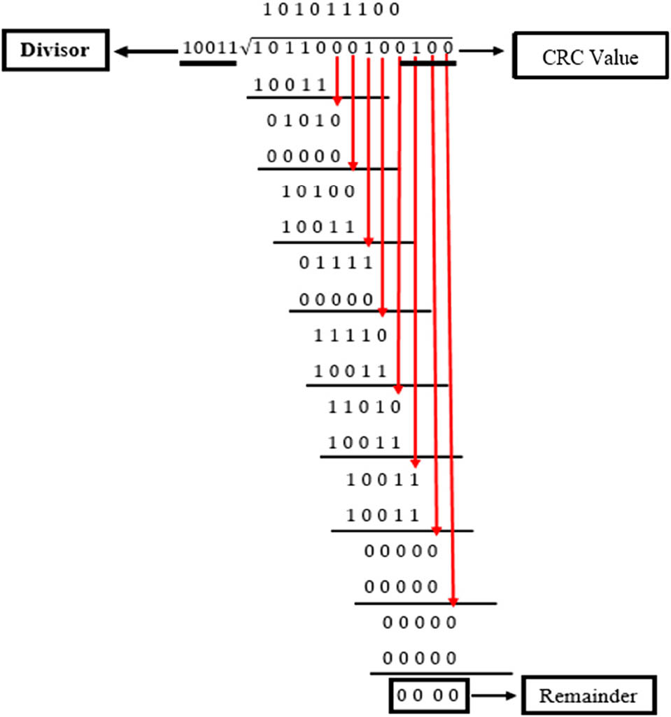
Figure 13
Manual calculation of the CRC Algorithm on the transmitter part.
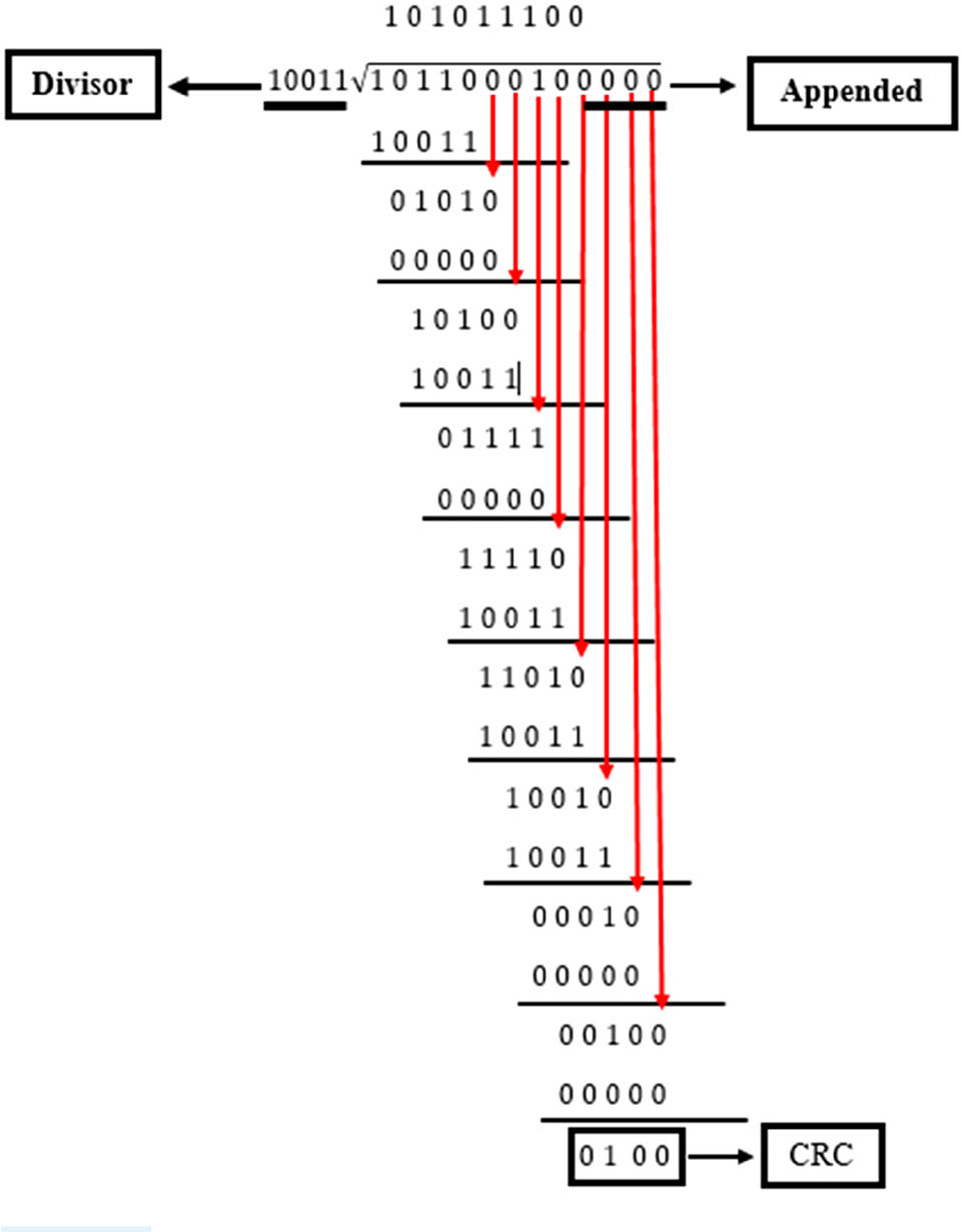
Figure 14
Manual calculation of the CRC Algorithm on the receiver part.
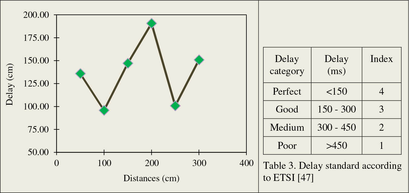
Figure 15
The testing of delay from QoS.
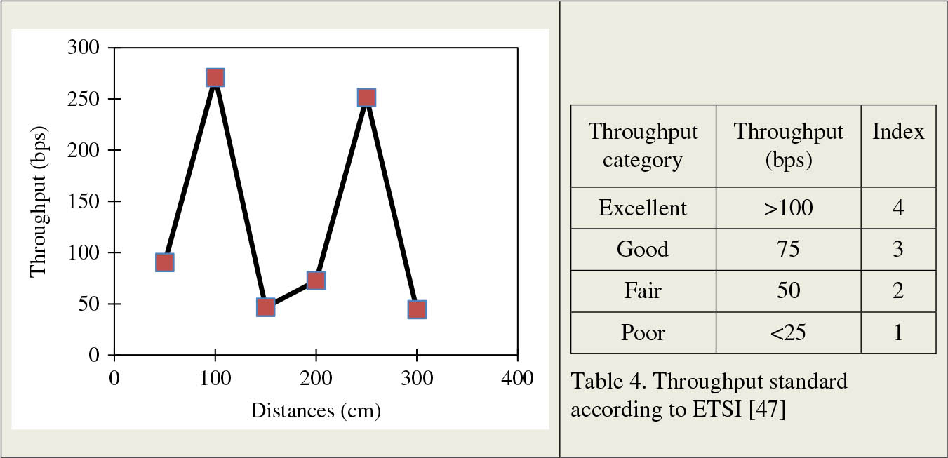
Figure 16
Throughput test results.
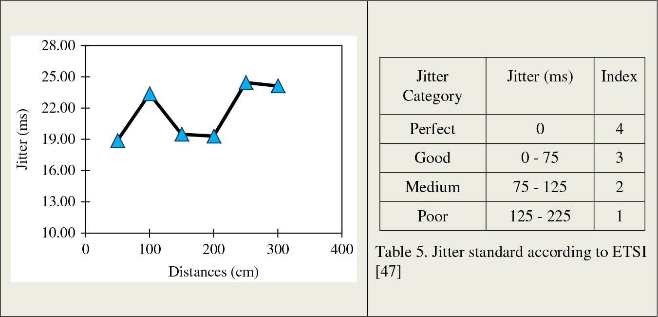
Figure 17
The testing of Jitter parameter from QoS.
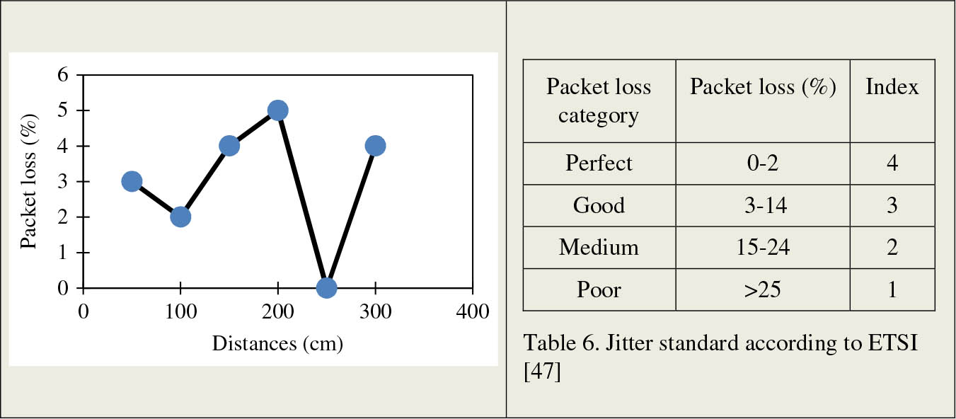
Figure 18
Average test value on packet loss of QoS.