
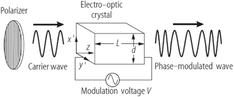
Figure 1
Applied electric field along z-direction changes the refractive index of crystal.
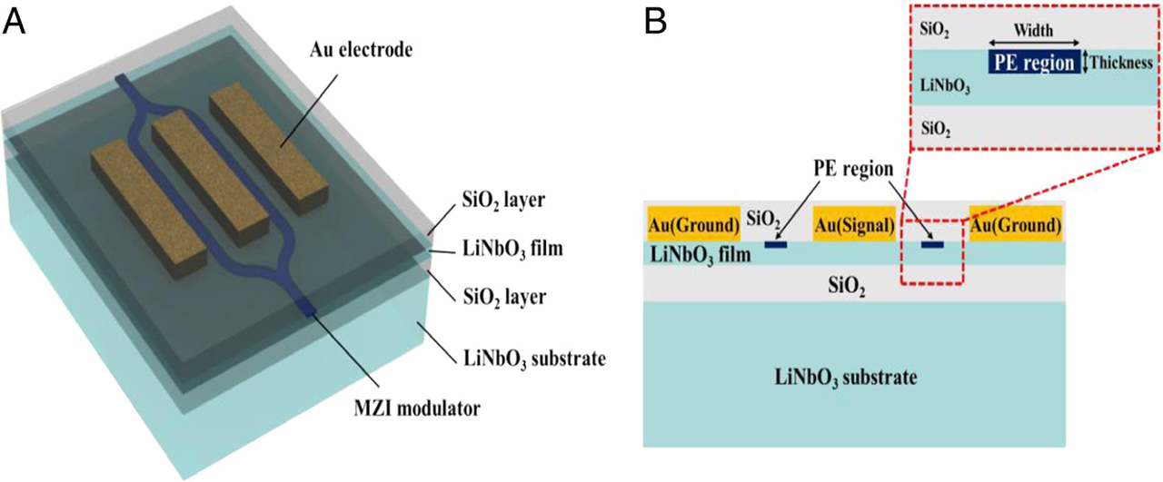
Figure 2
(a) A Mach–Zehnder interferometer modulator MZIM. (b) The cross-sectional diagram of the MZIM and the channel of the waveguides.
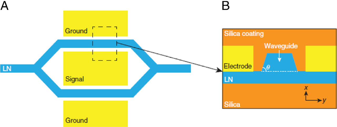
Figure 3
Integrated LN Mach-Zehnder modulator MZM: (a) top view and (b) cross-section area.
Table 1
Electro-optic coefficients (r33), refractive index (no) and wavelengths (λ), for LN.4.
| r33 (pm/V) | Wavelength (nm) | no | Reference |
|---|---|---|---|
| 31 | 633 | 2.2864 | (Casson et al., 2004) |
| 25 | 1560 | 2.2108 | (Casson et al., 2004) |
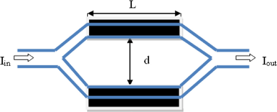
Figure 4
MZI electro-optic modulator based on LiNbO3.
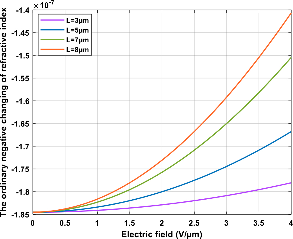
Figure 5
The ordinary negative changing of refractive index by applying electric field versus different lengths of arms.
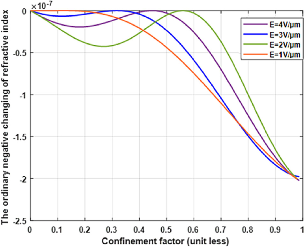
Figure 6
The ordinary negative changing of refractive index as a function of the confinement factor under different intensity of the applied electrical field.
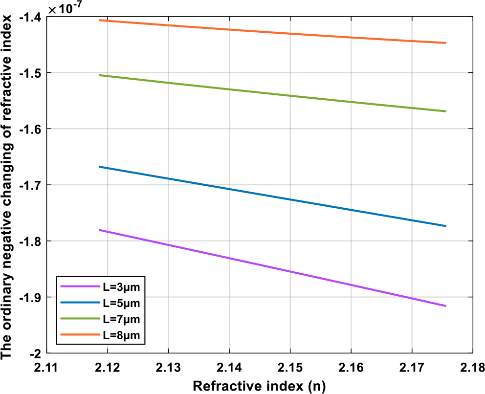
Figure 7
The ordinary negative changing of refractive index as a function of refractive index versus different lengths of arms for LiTaO3.
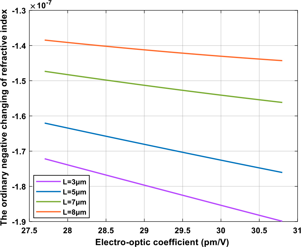
Figure 8
The ordinary negative changing of refractive index as a function of electro-optic coefficient versus different lengths of arms for LiTaO3.
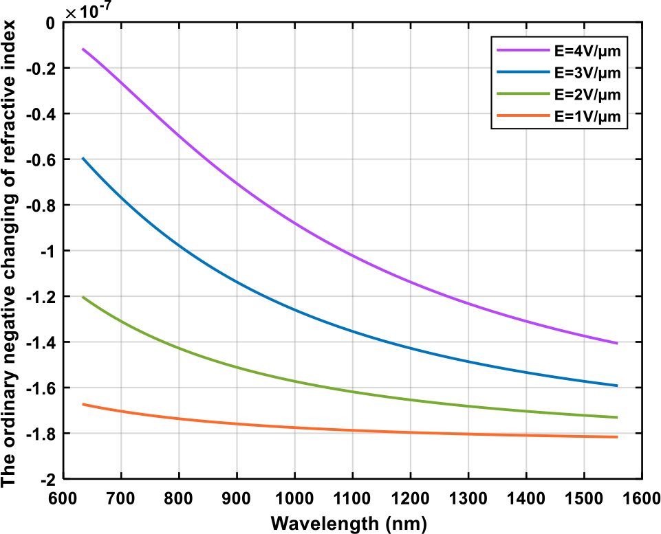
Figure 9
The ordinary negative changing of refractive index with wavelength under different applied electric fields for LiTaO3.
Table 2
The comparison between the reference paper (Chang et al., 2017; Qi and Li, 2020) and this work.
| Reference | Δn | L | d | ΔØ | E | Γ | Modulator type |
|---|---|---|---|---|---|---|---|
| (Qi and Li, 2020) and (He et al., 2019) | Large | Large In mm | Small | π/2 | E = V/d | Large | Transvers |
| This work | Large | Small In μm | – | π | E = V/L | Large | Longitudinal |