
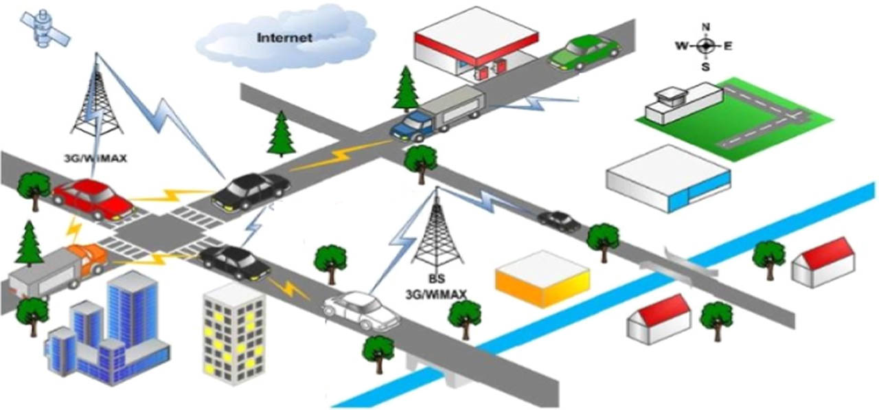
Figure 1
V2V Communication model.
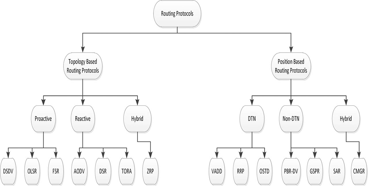
Figure 2
VANET routing protocols.
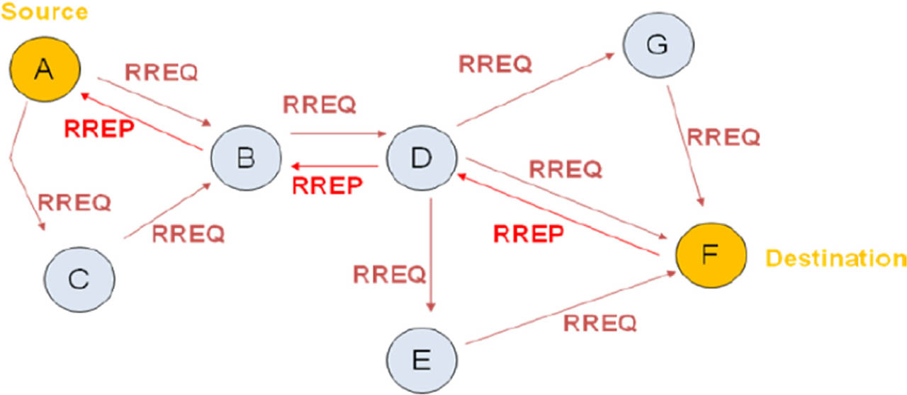
Figure 3
AODV control messages (Elbadr and Zubi, 2013).
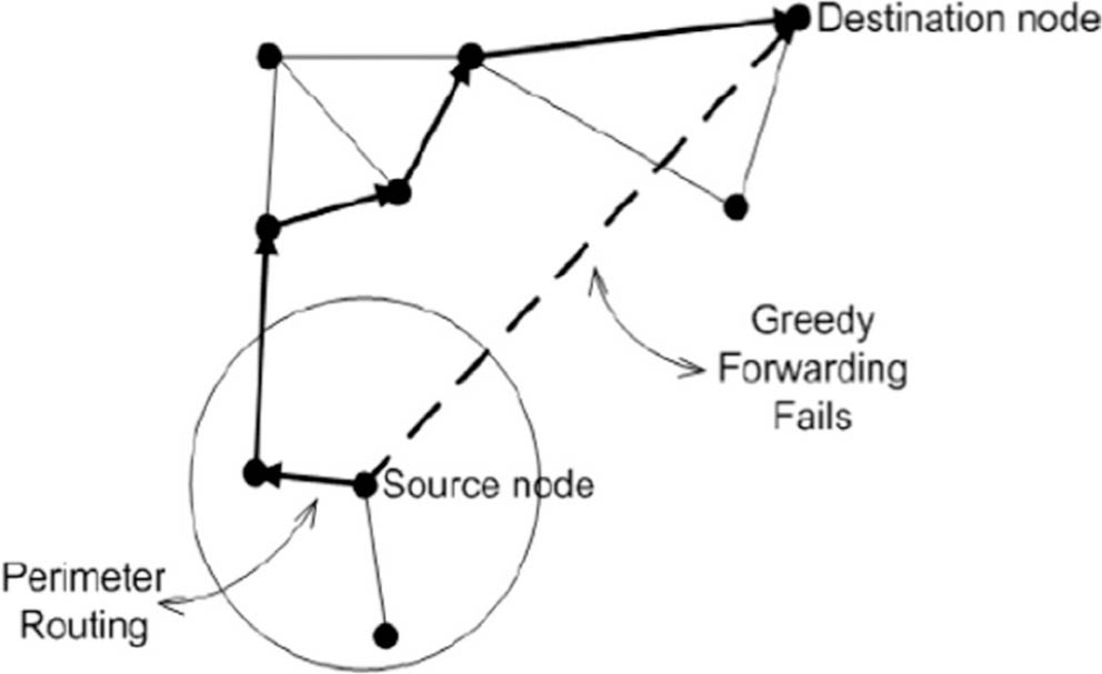
Figure 4
GSPR routing technique (Rao et al., 2008).
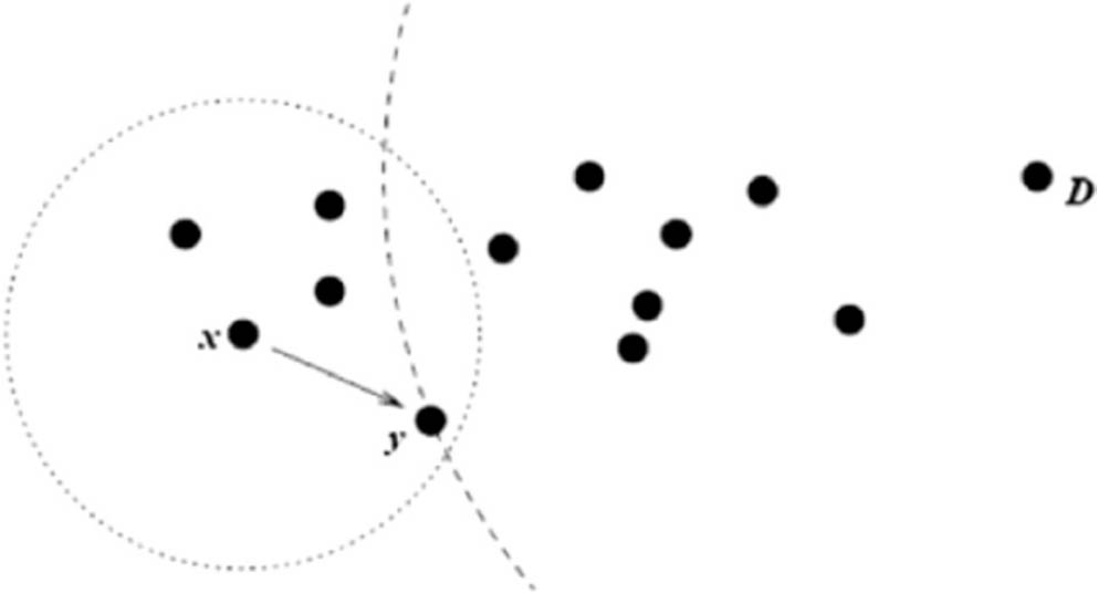
Figure 5
GSPR routing technique (Seet et al., 2004).
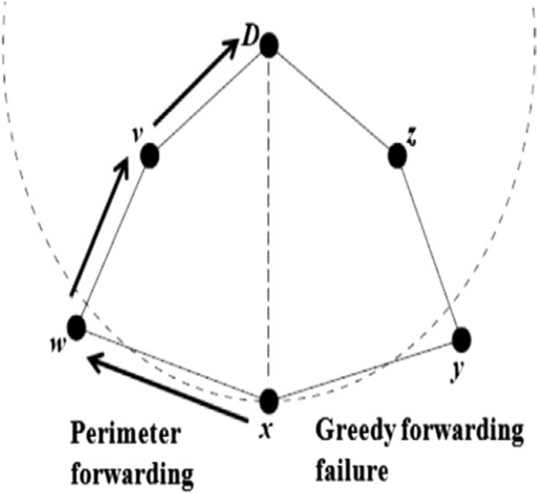
Figure 6
GSPR routing technique (Seet et al., 2004).
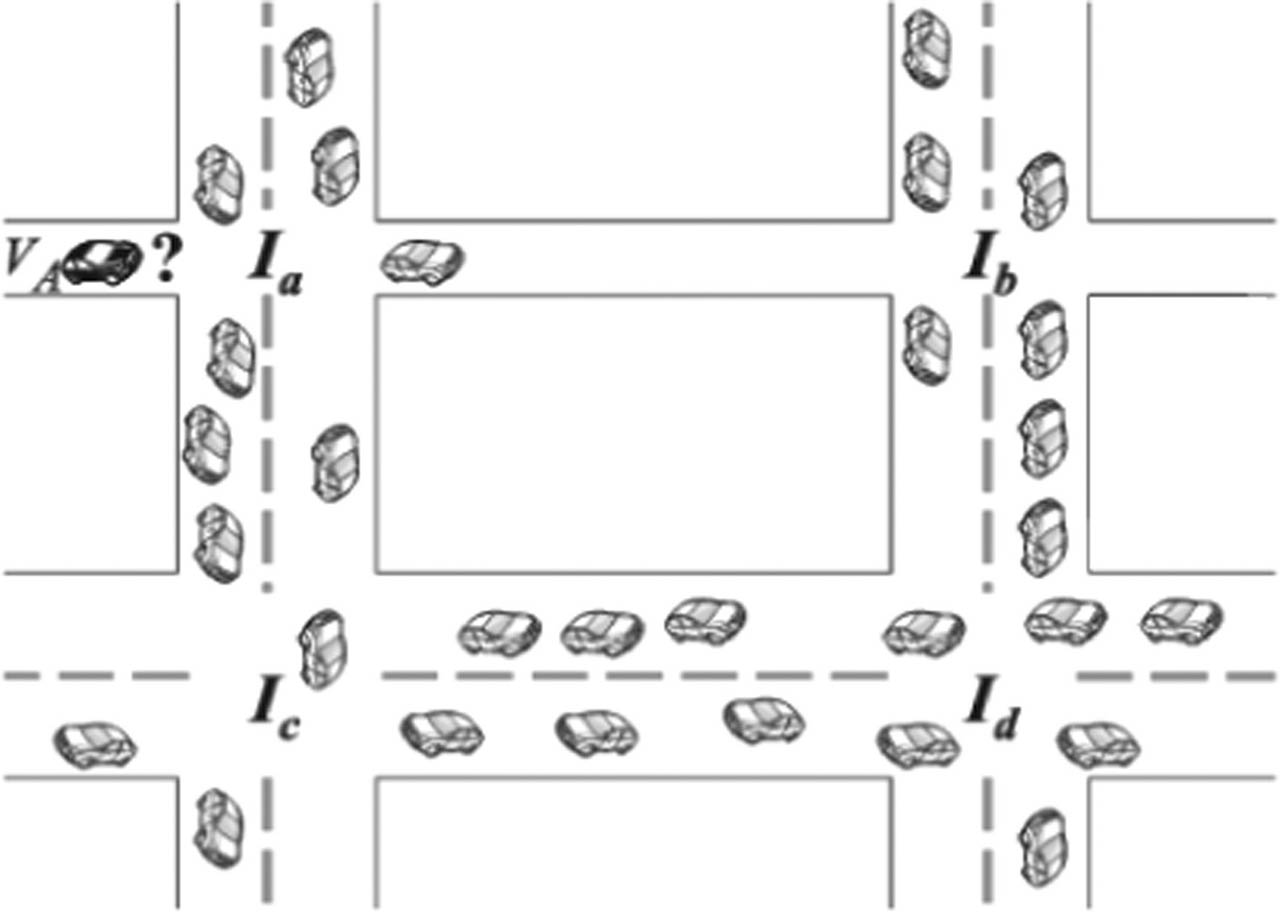
Figure 7
VADD routing technique (Shafiee and Leung, 2011).
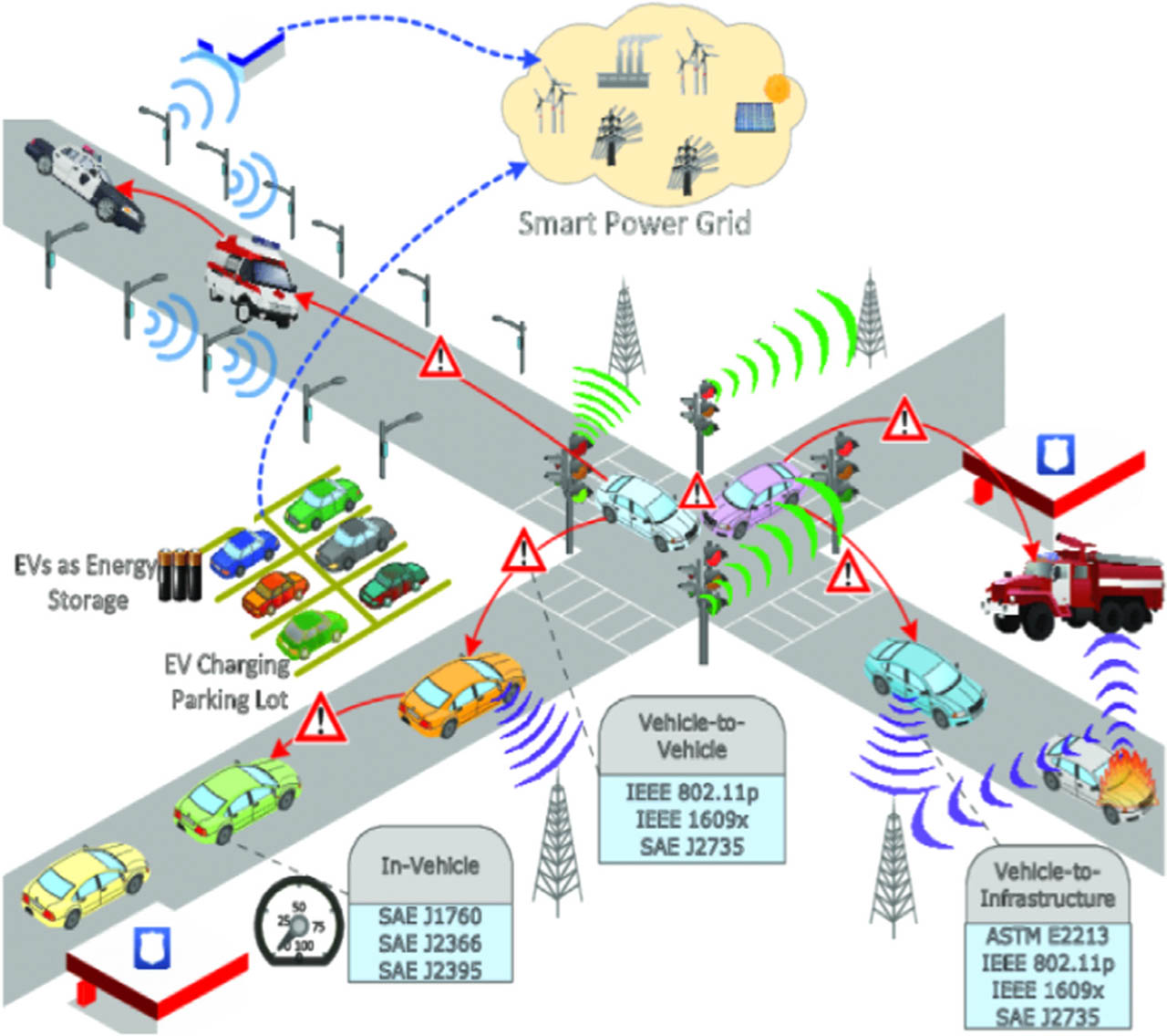
Figure 8
Proposed ITS architecture.
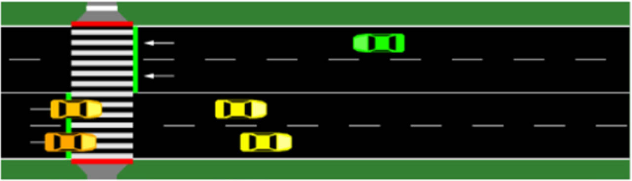
Figure 9
High traffic scenario—NS2.
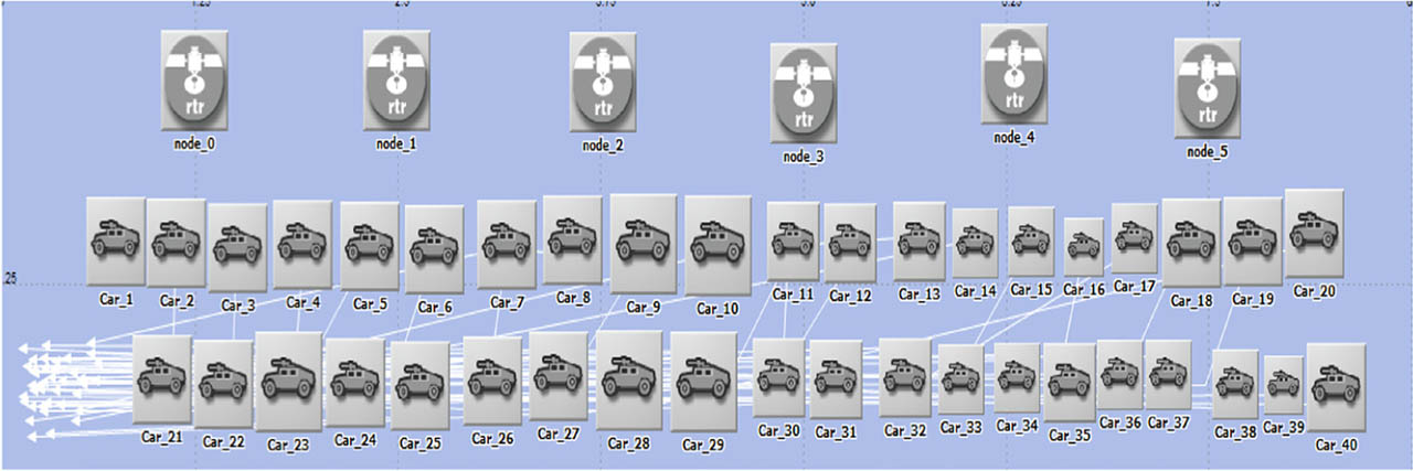
Figure 10
High traffic scenario—RIVERBED.
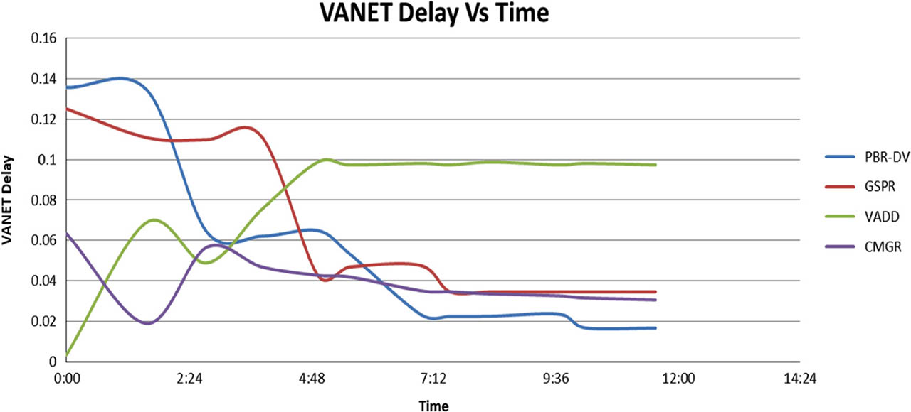
Figure 11
VANET delay.
Table 1
Simulation parameters.
| Parameter | Value |
|---|---|
| Total simulation time | 12 min |
| Simulation area | 9000 m × 1000 m |
| Total no. of vehicles | 50 vehicles |
| Vehicles mobility | Random starting from 0 to 40 km/hr |
| Mobility model | Random waypoint model |
| Number of lanes | 2 |
| IEEE 802.11p data rate | 1 Mbps |
| Channel bandwidth | 2 Mbps |
| Packet size | 512 bytes |
| Transmission range per hop | 250 m |
| Node processing delay | sec |
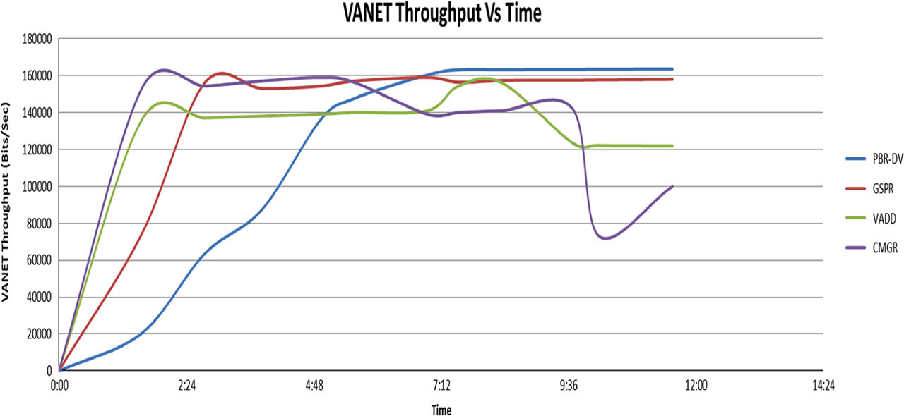
Figure 12
VANET throughput.
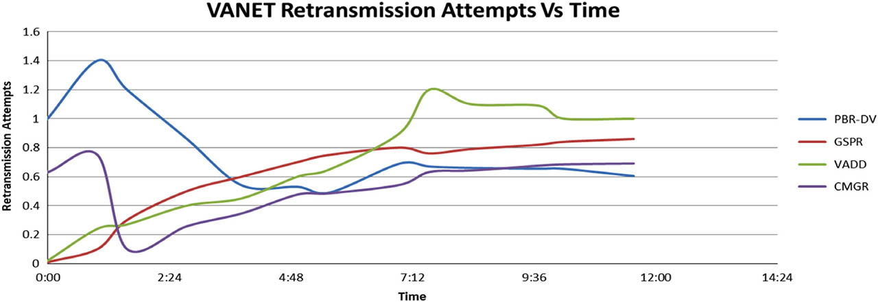
Figure 13
VANET retransmission attempts.
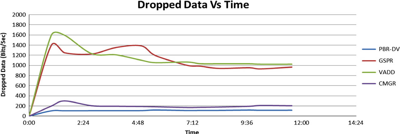
Figure 14
VANET dropped data.
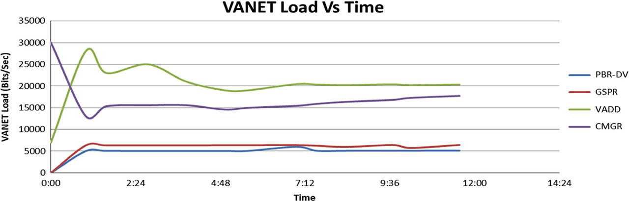
Figure 15
VANET load.
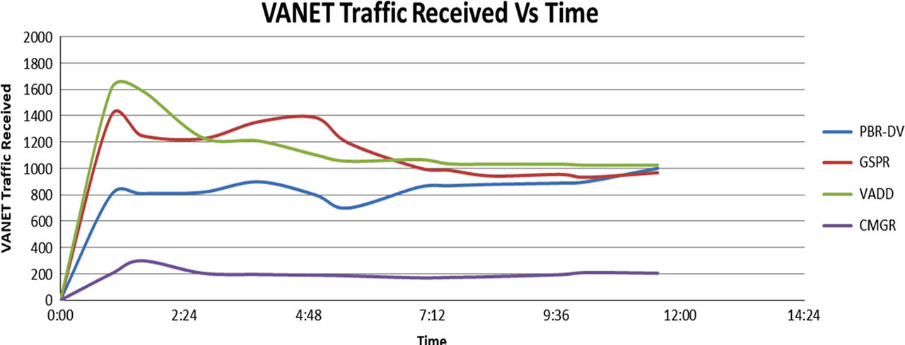
Figure 16
VANET traffic received.
Table 2
Summarize comparison between different protocols.
| KPI | PBR-DV | VADD | GSPR | CMGR |
|---|---|---|---|---|
| VANET delay | Very low | High | Low | Low |
| VANET Throughput | Very high | High | Very high | Low |
| VANET retransmission attempts | Very low | Very high | High | Low |
| VANET dropped data | Very low | Very High | Very high | Very low |
| VANET load | Very low | Very high | Very low | Very high |
| VANET traffic received | Very low | Very low | Very low | Very low |
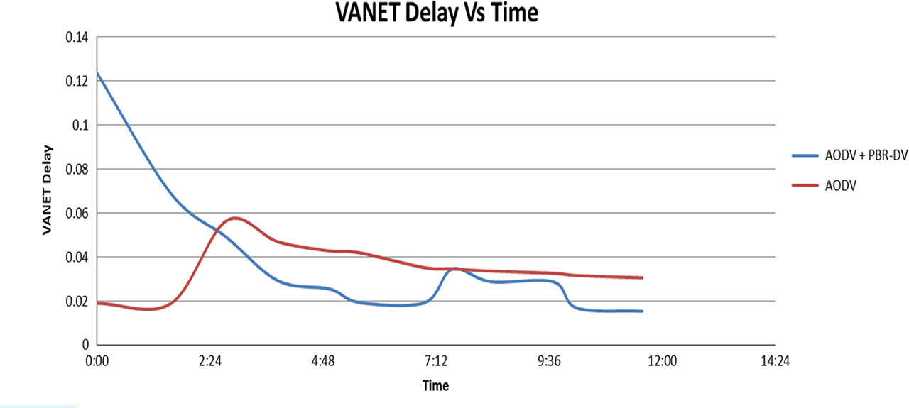
Figure 17
VANET delay.
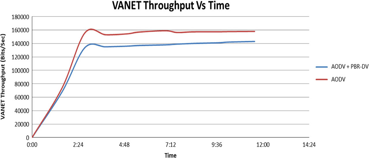
Figure 18
VANET throughput.
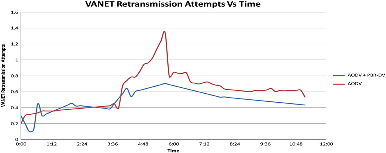
Figure 19
VANET retransmission attempts.
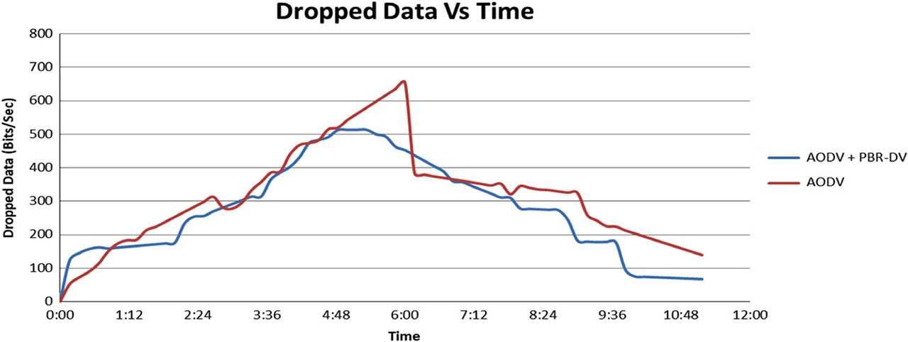
Figure 20
VANET dropped data.
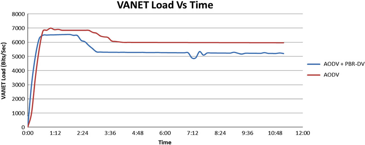
Figure 21
VANET load.
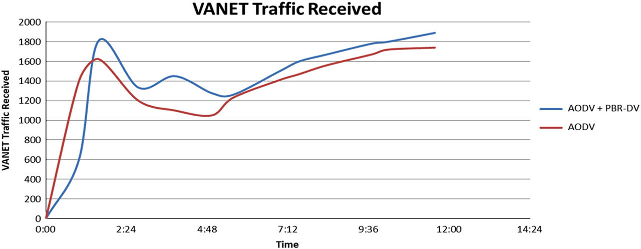
Figure 22
VANET traffic received.