
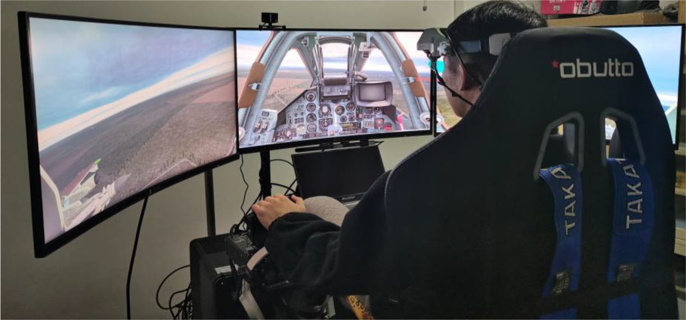
Figure 1.
Simulated flight environment experimental platform
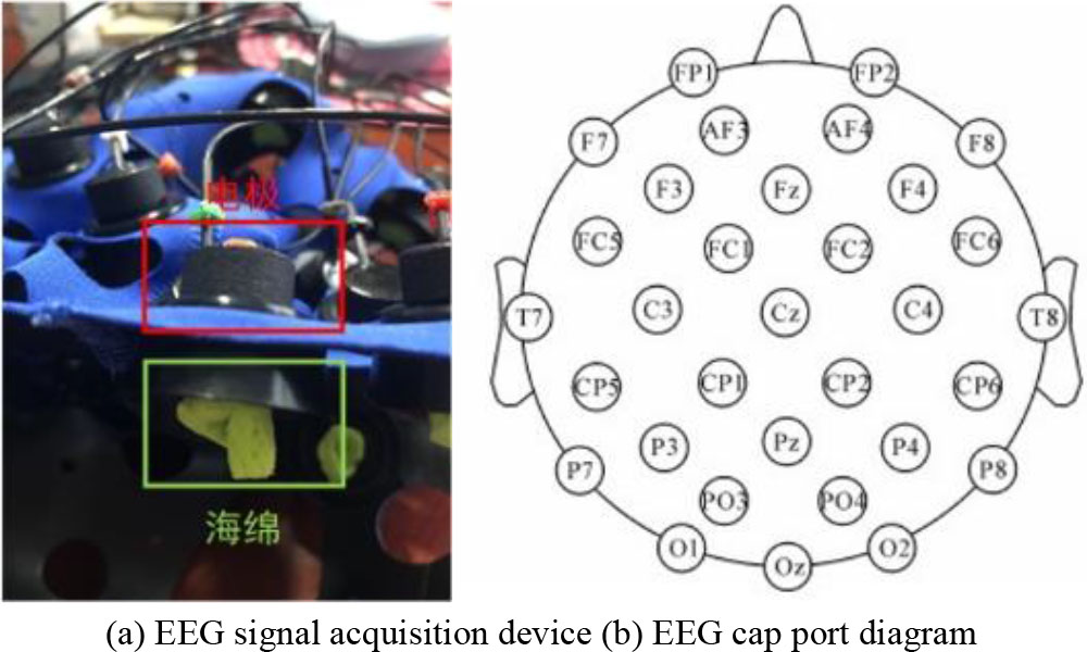
Figure 2.
ErgoLAB EEG device
TABLE I.
INFORMATION ON THE DIALS TO BE MONITORED FOR DIFFERENT DIFFICULTY TASKS
| High loads | Low loads | Control group |
|---|---|---|
| Indicated airspeed meter | Indicated airspeed meter | — |
| Pitching scale information | Pitching scale information | — |
| Altimeter information | Altimeter information | — |
| Directional angle information | — | — |
| Rolling corners information | — | — |
| Status of the steering compartment | — | — |
| Landing gear conditions | — | — |
| Engine status | — | — |

Figure 3.
Flow chart of data processing
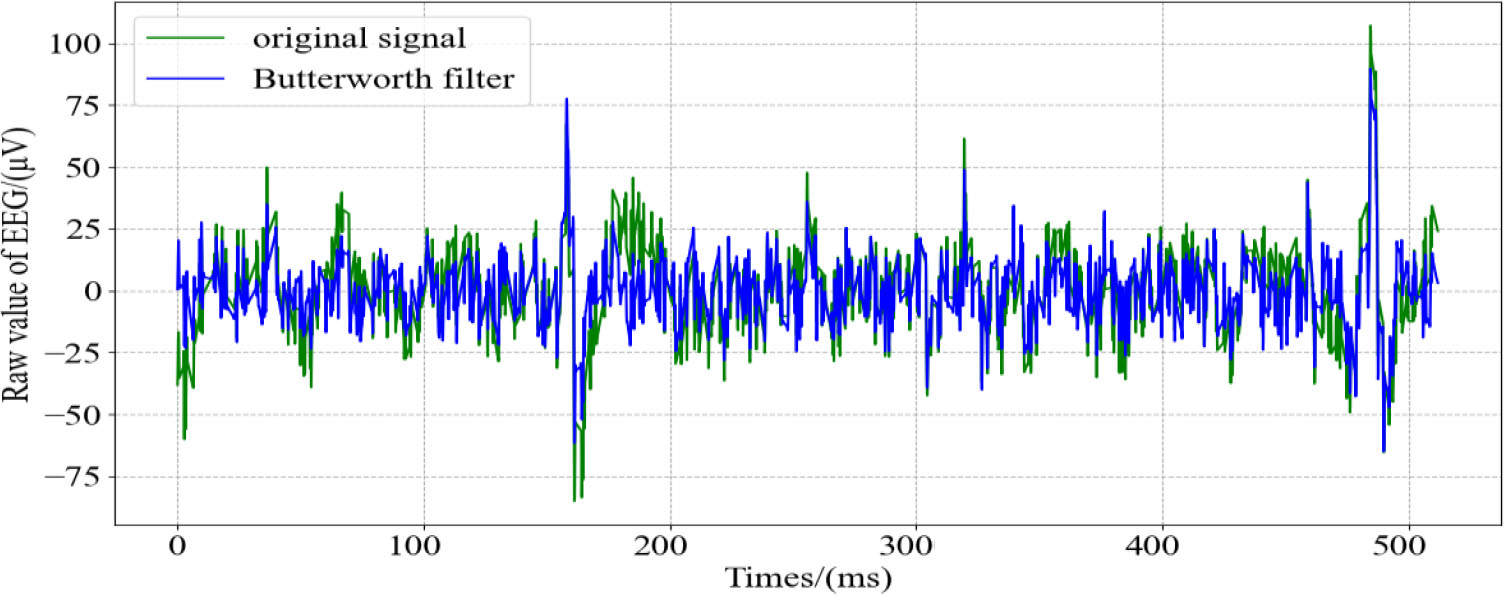
Figure 4.
Comparison of EEG waveforms before and after data processing
TABLE II.
TABLE OF FREQUENCY BANDS OF EEG SIGNALS
| Frequency band range(Hz) | Band names |
|---|---|
| 1-4 | delta (δ) |
| 4-8 | theta (θ) |
| 8-13 | alpha (α) |
| 13-30 | beta (β) |
| >30 | gamma (γ) |
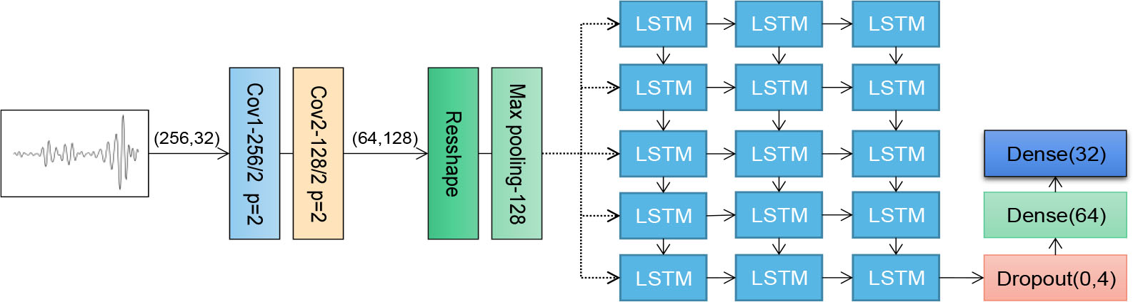
Figure 5.
Network model diagram
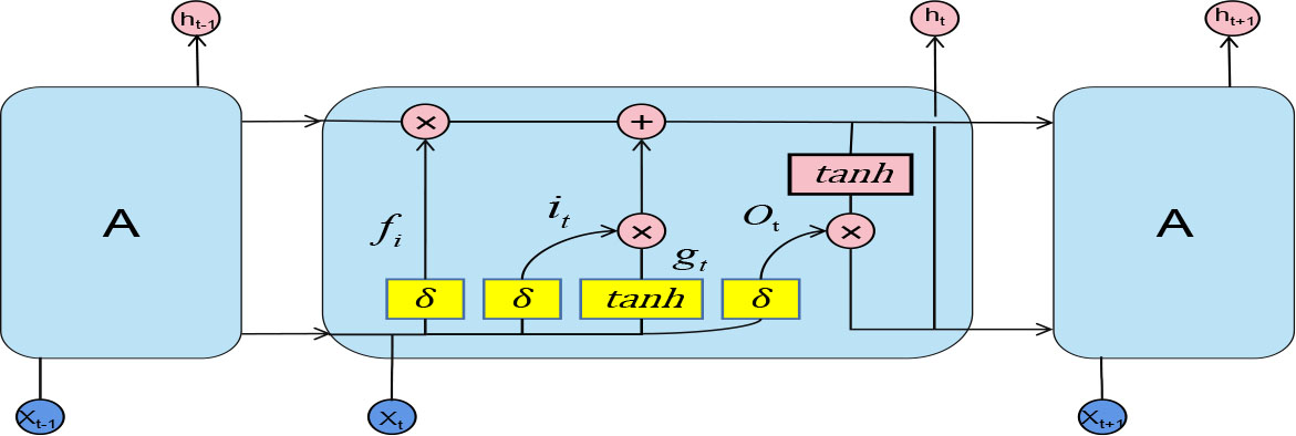
Figure 6.
LSTM structure diagram
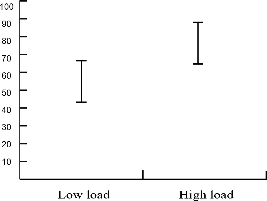
Figure 7.
NASA-TLX evaluation results
TABLE III.
MODEL TRAINING PARAMETERS
| Name of the layer | Hyperparameters | Input vector | Output vector |
|---|---|---|---|
| EEG_Input | None | (256,1) | (256,1) |
| Conv1D | Kernel size=5 | ||
| stride = 2 | (256,1) | (128,64) | |
| Conv2D | Kernel size=3 | ||
| stride = 2 | (128,64) | (64,128) | |
| Reshape | None | (64,128) | (8192,1) |
| Max Pooling | pool size=128 | (8192,1) | (64,1) |
| LSTM | units=32 | (64,1) | (32,1) |
| Dense | units=64 | (32,1) | (64,1) |
| Dense | units=32 | (64,1) | (32,1) |
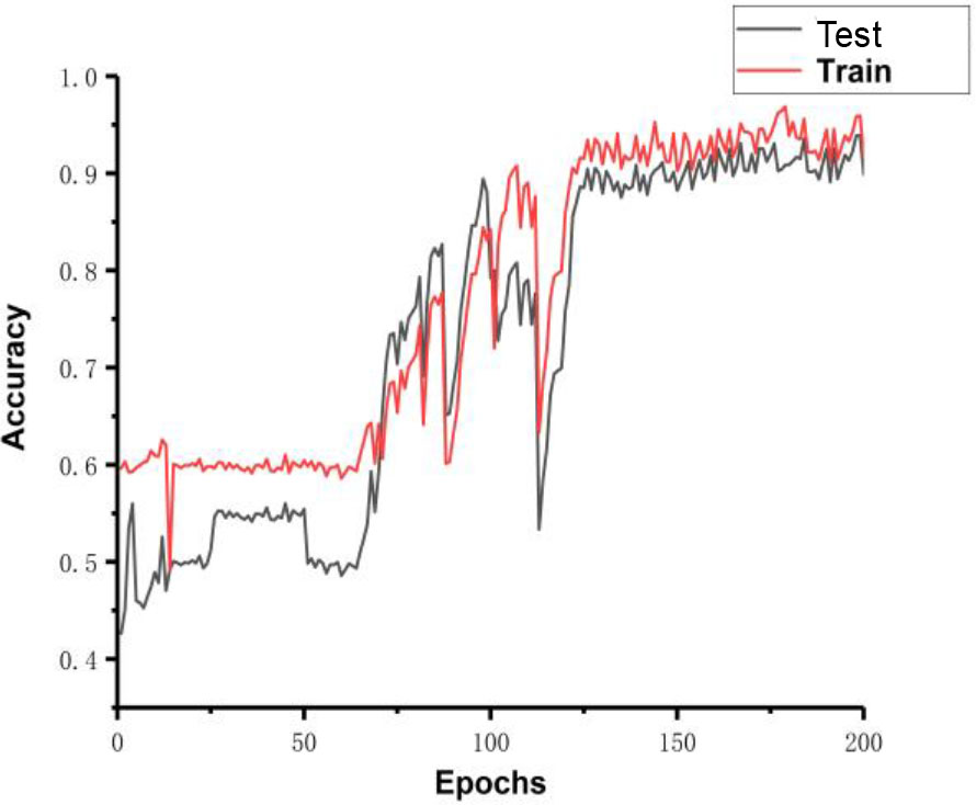
Figure 8.
Training and test set accuracy
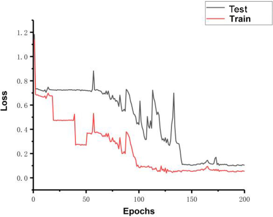
Figure 9.
Loss rate for training and test sets