
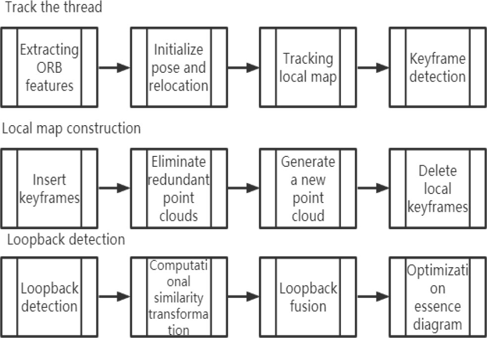
Figure 1.
Key threads for ORB-SLAM
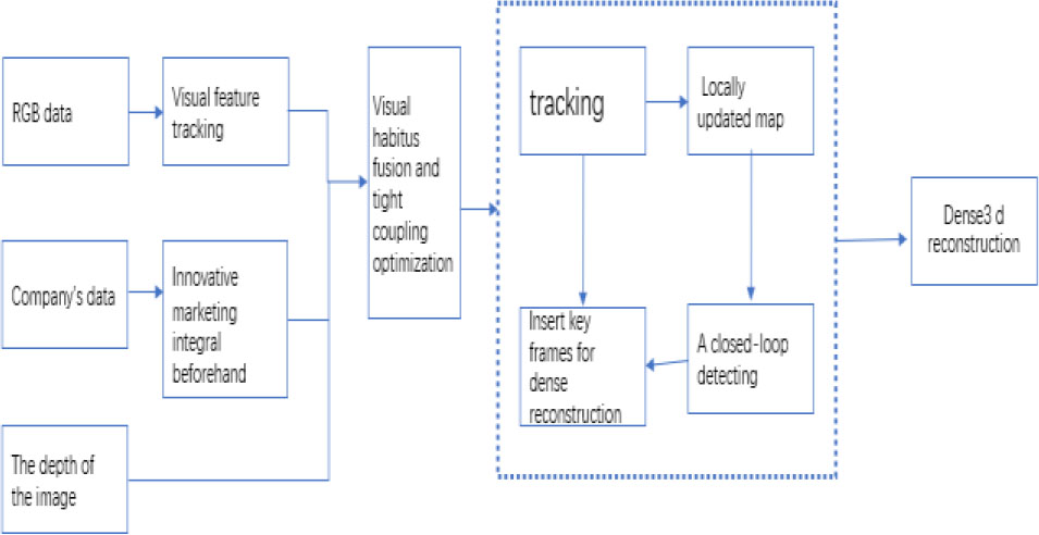
Figure 2.
STRUCTURE diagram of 3D reconstruction
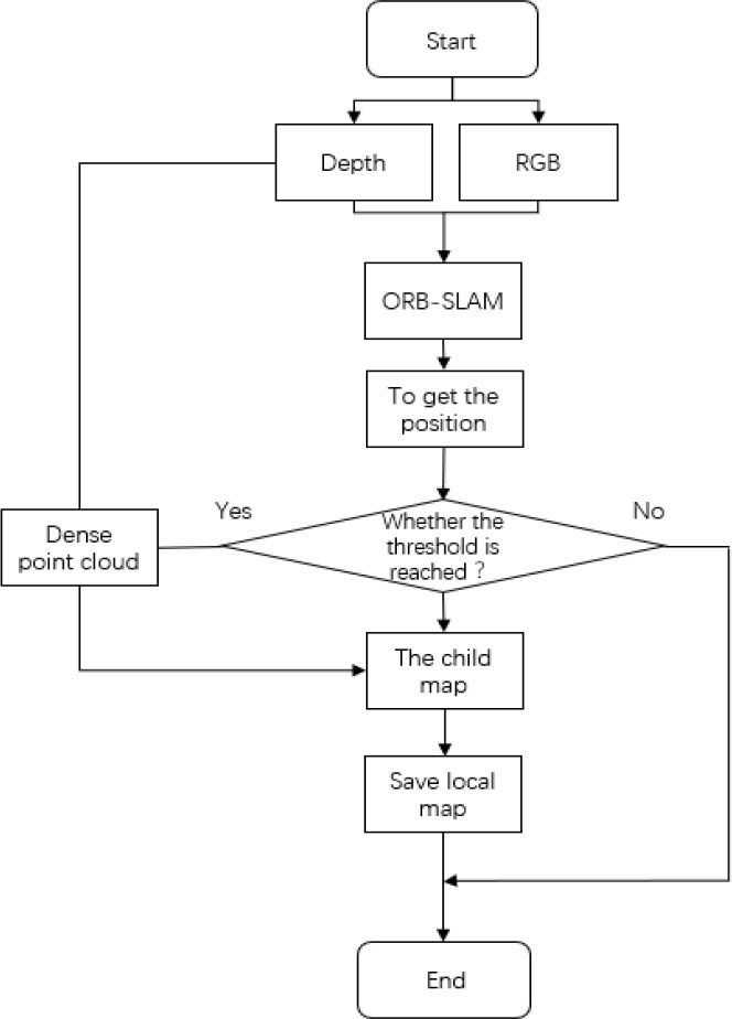
Figure 3.
ORB-SLAM algorithm flow
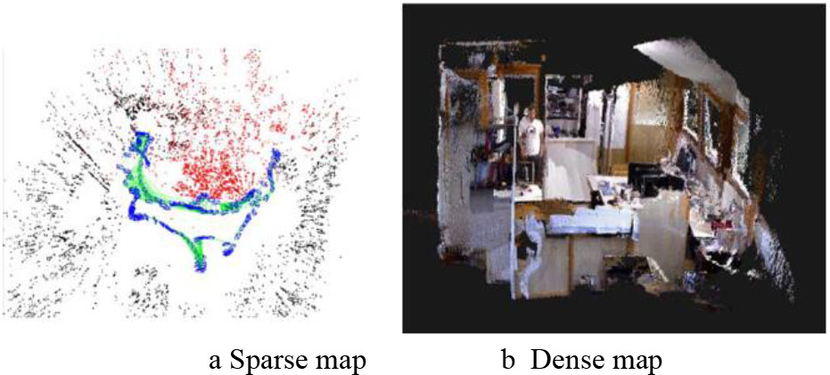
Figure 4.
Dense reconstruction results of data set FR1_room
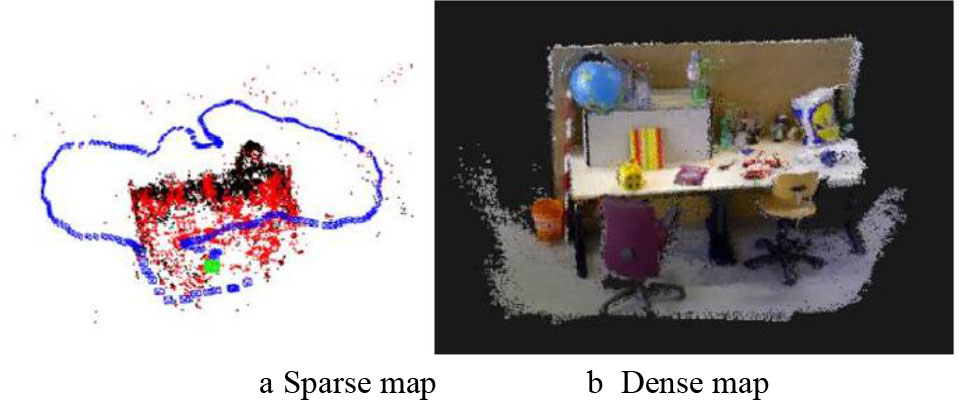
Figure 5.
Dense reconstruction results of data set FR3_office
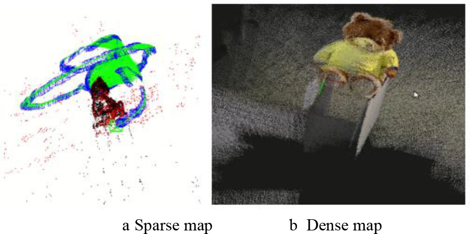
Figure 6.
Reconstruction results of dataset RGBD_DATASet_freiburg3_TEDDY
TABLE I.
Hardware configuration parameters of the robot
| Hardware | Model |
|---|---|
| Upper-computer workstation | Lenovo Air15 |
| IMU sensor | MPU9250 |
| Depth sensor | Realsense D435 |
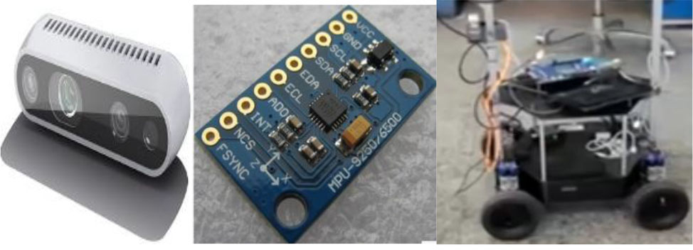
Figure 7.
Depth camera schematic diagram
TABLE II.
Software system configuration
| The name of the software | Model and Version |
|---|---|
| The operating system | Ubuntu18.04 |
| Robot operating system | ROS-Melodic |
| Development programming language | c/c++ |
| opencv | |
| Visual library to use Point cloud library | PCL |
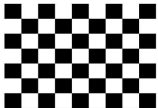
Figure 8.
Schematic diagram of checkerboard calibration board
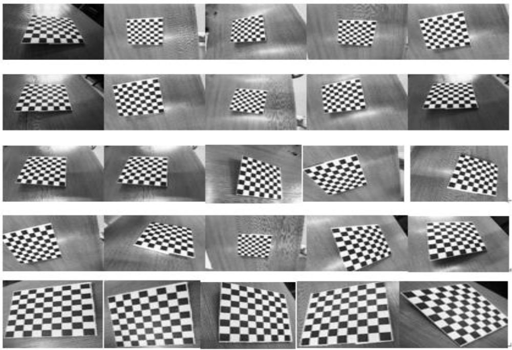
Figure 9.
Schematic diagram of multi-angle calibration plate
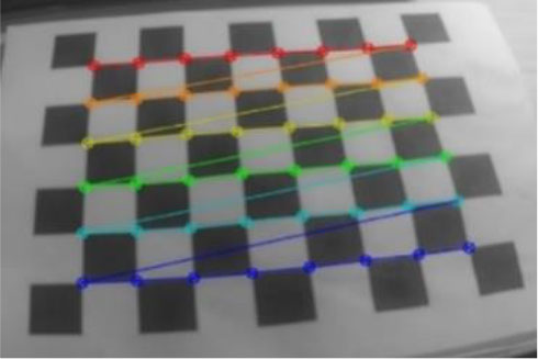
Figure 10.
Corner extraction of the calibration board
TABLE III.
Calibration results of the realsense D435 camera
| The camera parameters | The calibration results | ||
|---|---|---|---|
| Internal | 605.894 | 0 | 317.887 |
| 0 | 606.856 | 256.416 | |
| 0 | 0 | 1 | |
| Distortion parameter 1 | 0.15689 | ||
| Distortion parameter 2 | −0.3425 | ||
| Mean reprojection difference | 0.28213 | ||
TABLE IV.
Calibration results of multiple sensors
| The camera parameters | The calibration results | ||
|---|---|---|---|
| Rotation matrix of camera and IMU | 0.9999524 | 0.0042236 | 0.0012432 |
| −0.0054268 | 0.9995236 | 0.00158425 | |
| −0.001426238 | 0.0017052 | 0.9999842 | |
| Translation matrix of camera and IMU | 0.01238847 | 0.00842635 | −0.02145263 |
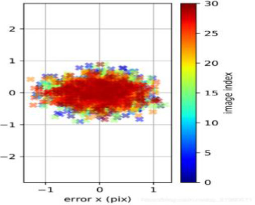
Figure 11.
Reprojection error diagram
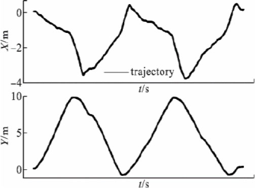
Figure 12.
Displacement curve in XY direction
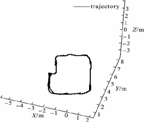
Figure 13.
Trajectory diagram of the robot
TABLE V.
Experimental results of 3D reconstruction for different sensors
| Sensor | Track the percentage of partial breaks caused by loss |
|---|---|
| Without IMU | 35% |
| With IMU | 10% |
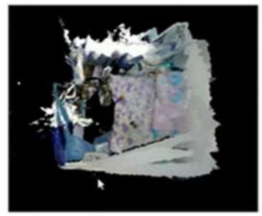
Figure 14.
Top view of adding an IMU
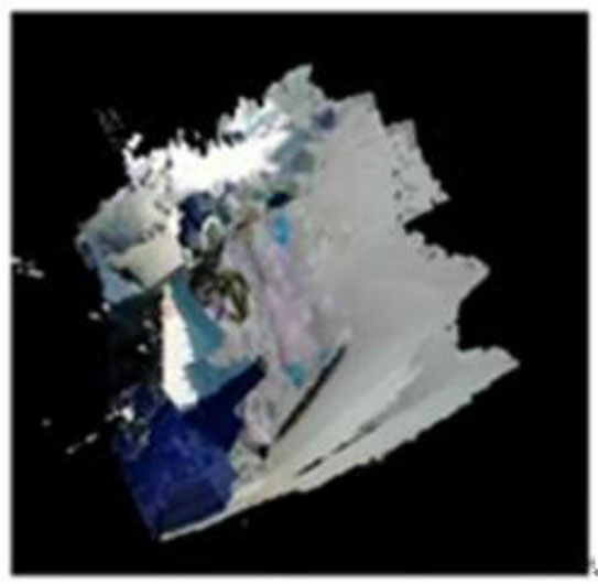
Figure 15.
Top view of adding an IMU without an IMU