
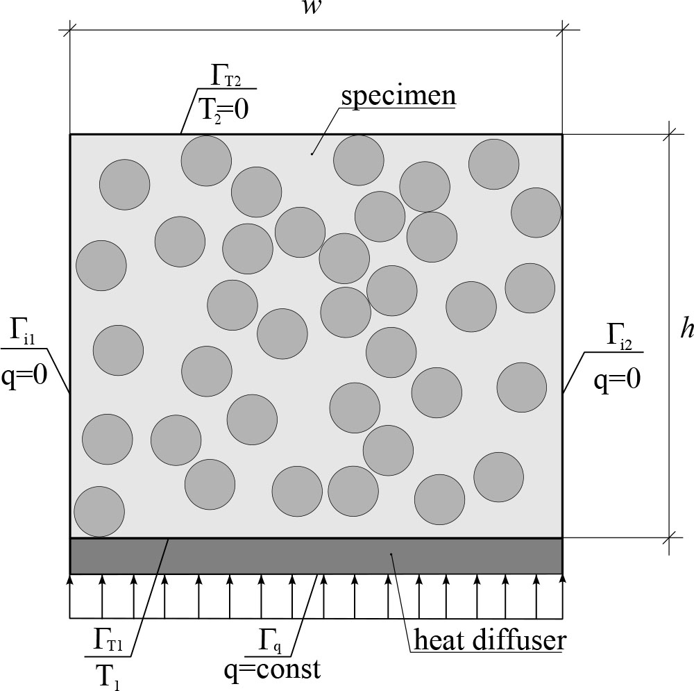
Fig. 1.
Schematic diagram of the virtual experimental setup
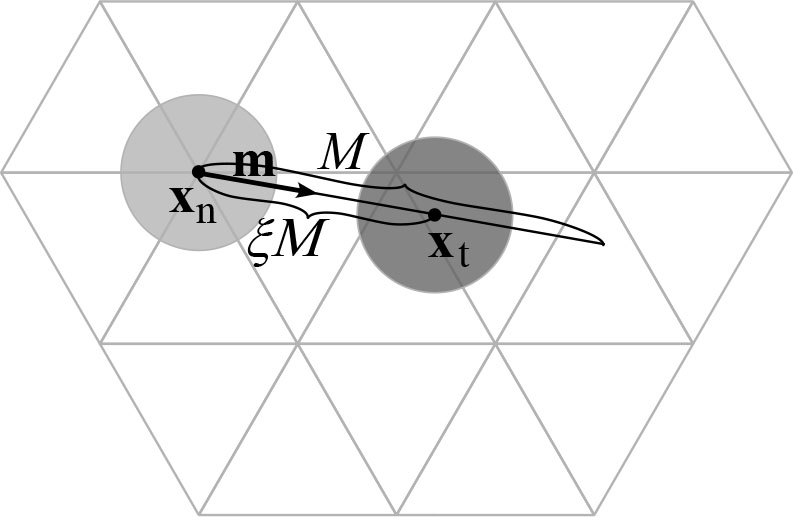
Fig. 2.
Schematic of the fiber displacement to a random position
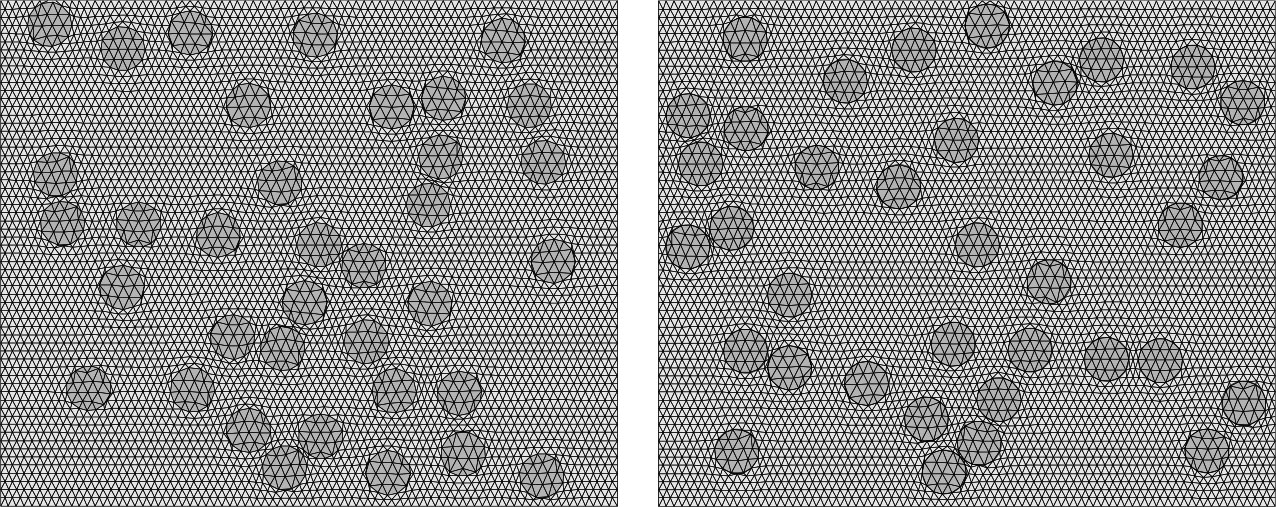
Fig. 3.
Example of random fiber distribution for ρ = 0.20
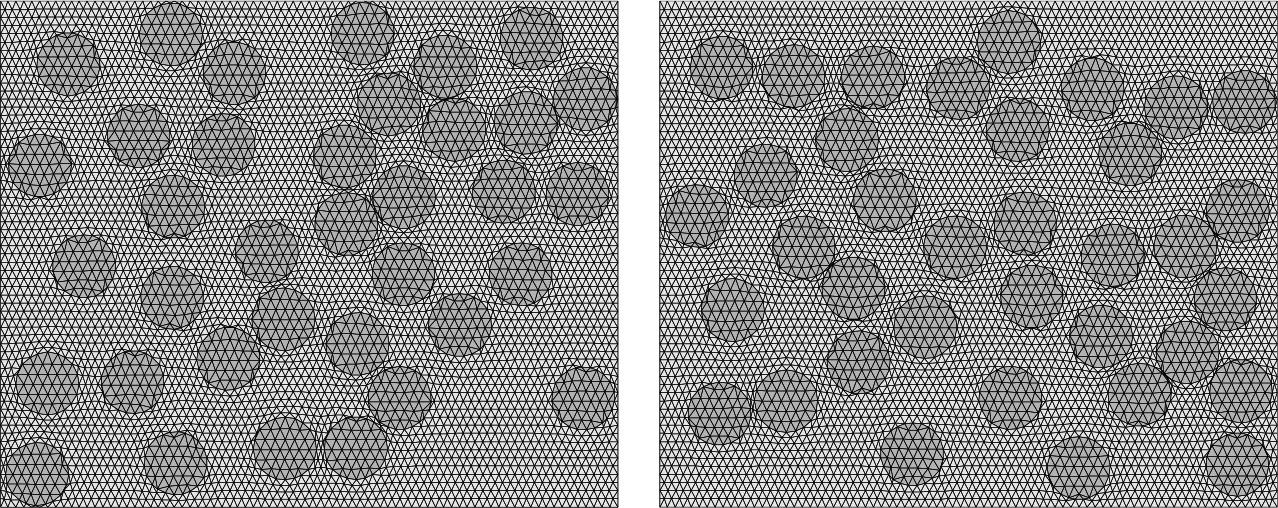
Fig. 4.
Example of random fiber distribution for ρ = 0.40
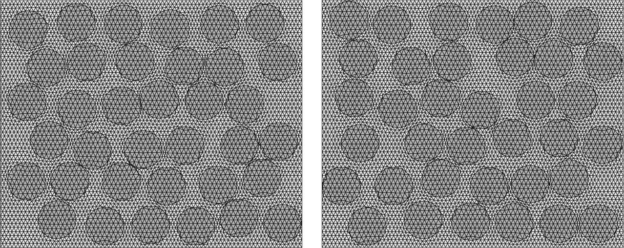
Fig. 5.
Example of random fiber distribution for ρ = 0.60
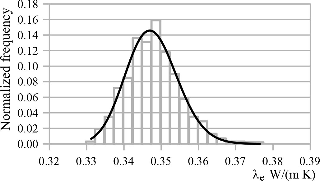
Fig. 6.
Histogram and gamma distribution for λf =10, ρ=0.3
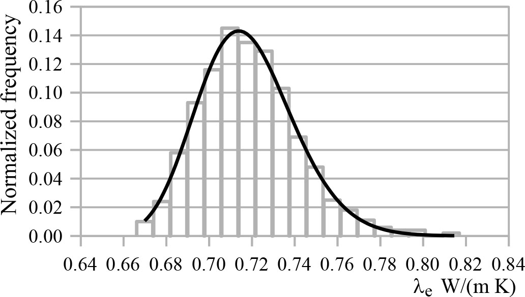
Fig. 7.
Histogram and gamma distribution for λf =10, ρ=0.6
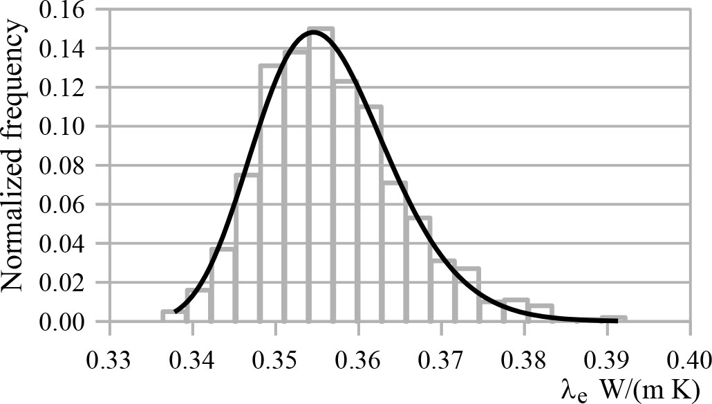
Fig. 8.
Histogram and gamma distribution for λf =100, ρ=0.3
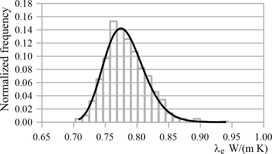
Fig. 9.
Histogram and gamma distribution for λf =100, ρ=0.6
Table 1.
Gamma distribution parameters for λf =10 W/(m·K)
| ρ | α | β | σ | Mode | StdDev |
|---|---|---|---|---|---|
| 0.2 | 20.0 | 7.80E-04 | 0.267 | 0.282 | 3.49E-03 |
| 0.3 | 88.7 | 7.34E-04 | 0.283 | 0.347 | 6.91E-03 |
| 0.4 | 25.1 | 2.58E-03 | 0.370 | 0.432 | 1.29E-02 |
| 0.5 | 20.0 | 3.62E-03 | 0.476 | 0.545 | 1.62E-02 |
| 0.6 | 31.8 | 3.99E-03 | 0.591 | 0.714 | 2.25E-02 |
Table 2.
Gamma distribution parameters for λf =100 W/(m·K)
| ρ | α | β | σ | Mode | StdDev |
|---|---|---|---|---|---|
| 0.2 | 20.0 | 8.88E-04 | 0.269 | 0.286 | 3.97E-03 |
| 0.3 | 20.0 | 1.81E-03 | 0.320 | 0.355 | 8.09E-03 |
| 0.4 | 20.0 | 3.43E-03 | 0.386 | 0.451 | 1.53E-02 |
| 0.5 | 20.0 | 4.41E-03 | 0.494 | 0.578 | 1.97E-02 |
| 0.6 | 20.0 | 7.02E-03 | 0.641 | 0.775 | 3.14E-02 |
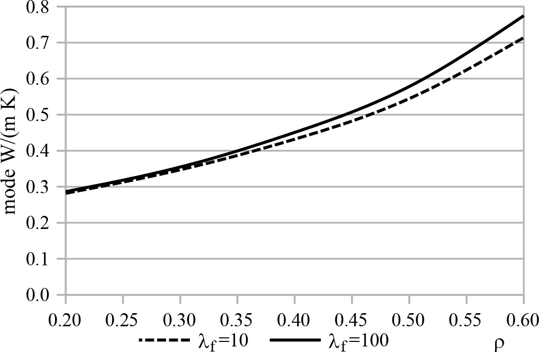
Fig. 10.
Modes as a function of the fiber volume fraction in the composite matrix
Table 3.
Extreme values of the effective thermal conductivity and their relative difference for λf =10 W/(m·K)
| ρ | min W/(m·K) | max W/(m·K) | RD |
|---|---|---|---|
| 0.2 | 0.274 | 0.295 | 0.079 |
| 0.3 | 0.330 | 0.377 | 0.145 |
| 0.4 | 0.403 | 0.487 | 0.208 |
| 0.5 | 0.508 | 0.628 | 0.236 |
| 0.6 | 0.666 | 0.817 | 0.227 |
Table 4.
Extreme values of the effective thermal conductivity and their relative difference for λf =100 W/(m·K)
| ρ | min W/(m·K) | max W/(m·K) | RD |
|---|---|---|---|
| 0.2 | 0.277 | 0.306 | 0.106 |
| 0.3 | 0.336 | 0.392 | 0.166 |
| 0.4 | 0.415 | 0.513 | 0.237 |
| 0.5 | 0.538 | 0.682 | 0.267 |
| 0.6 | 0.703 | 0.944 | 0.343 |
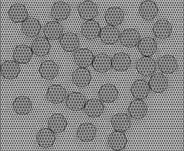
Fig. 11.
Fiber arrangement corresponding to the maximum thermal conductivity observed
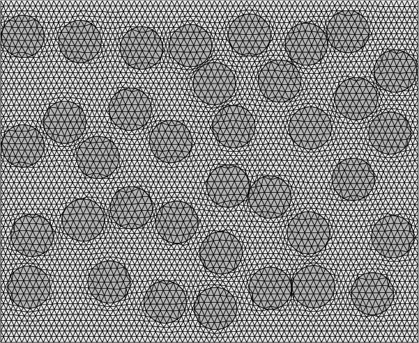
Fig. 12.
Fiber arrangement corresponding to the minimum thermal conductivity observed