
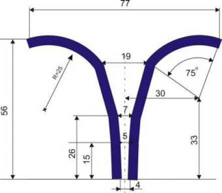
Fig.1.
Project of textile antenna
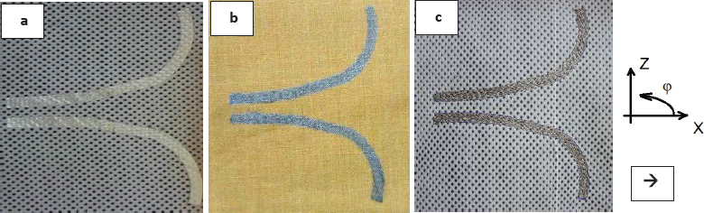
Fig.2.
Textile antennas with radiation: a)sputtered, b)printed, c)embroidered
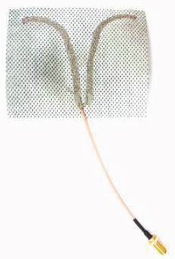
Fig.3.
Embroidered antenna connected to coaxial cable
Table 1.
Comparison of rS electroconductive paths
| Method of production | Magnetron sputtering | Ink-jet printing | Embroidery |
|---|---|---|---|
| Electroconductive factor | Ag | Ag nanoparticles | Yarn with Ag |
| Surface resistivity rS, Ωm/m | 0,05 | 2,83 | 1,20 |
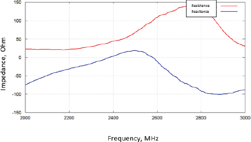
Fig.4.
Impedance of textile antenna made by magnetron sputtering (reactance – blue line, resistance – red line)
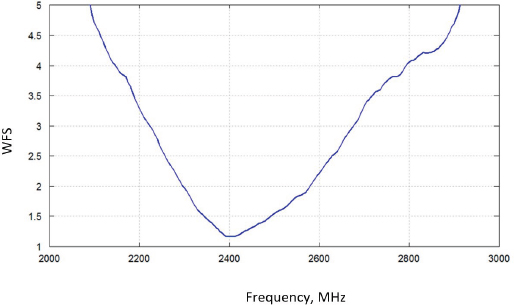
Fig.5.
Voltage standing wave ratio of antenna with sputtered radiator
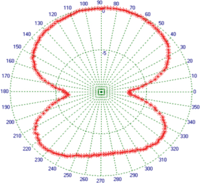
Fig.6.
Radiation pattern of antenna with a sputtered radiator in free space, normalized gain of the antenna in vertical polarization Gq(j,90) at a frequency of 2.4 GHz
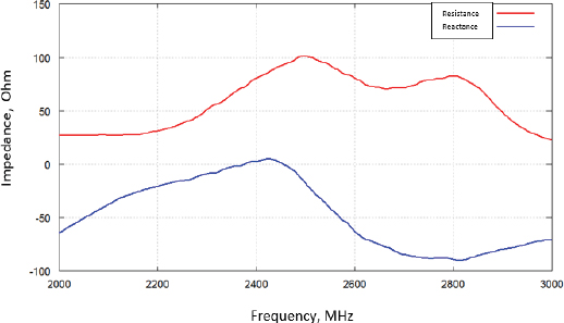
Fig.7.
Impedance of textile antenna made by printing (reactance – blue line, resistance – red line)
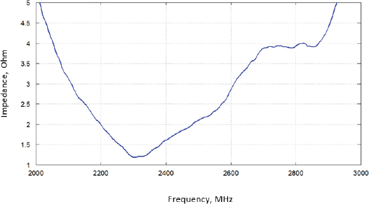
Fig.8.
Voltage standing wave ratio of antenna with printed radiator
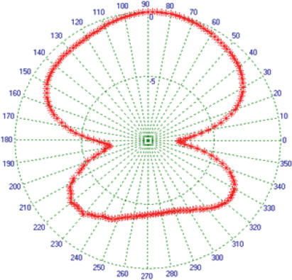
Fig.9.
Radiation pattern of antenna with a printed radiator in free space, normalized gain of the antenna in vertical polarization Gq(j,90) at a frequency of 2.4 GHz
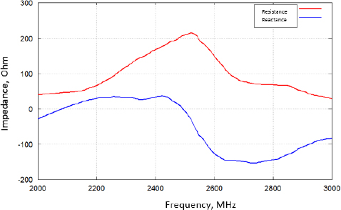
Fig.10.
Impedance of textile antenna made by embroidery (reactance – blue line, resistance – red line)
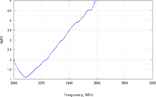
Fig.11.
Voltage standing wave ratio of antenna with embroidered radiator
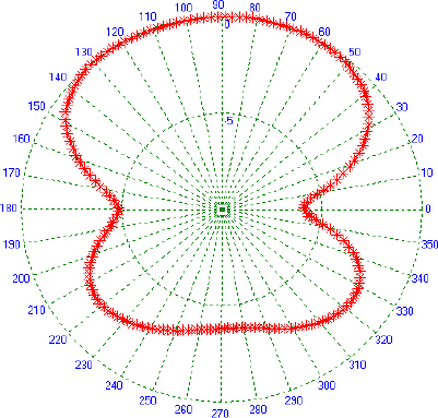
Fig.12.
Radiation pattern of antenna with a embroidered radiator in free space, normalized gain of the antenna in vertical polarization Gq(j,90) at a frequency of 2.4 GHz