

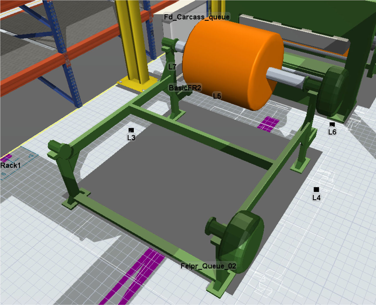
Figure 1
Part of the placed machine units in FlexSim (Source: Own study)
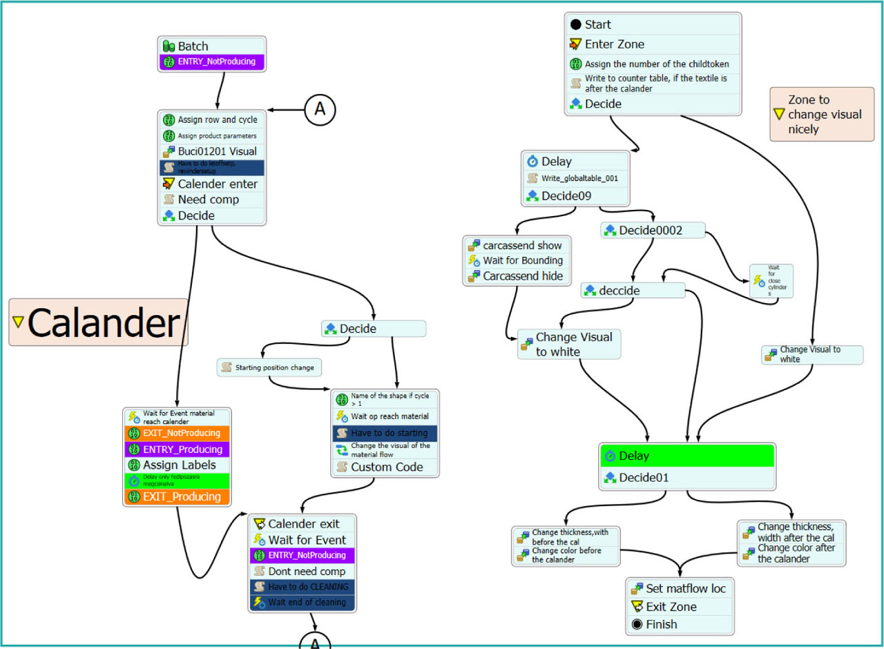
Figure 2
Part of Process Flow of the material flow (Source: Own study)
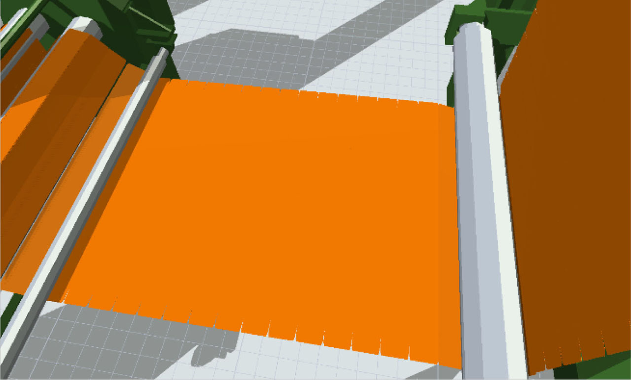
Figure 3
Continuous material flow (Source: Own study)
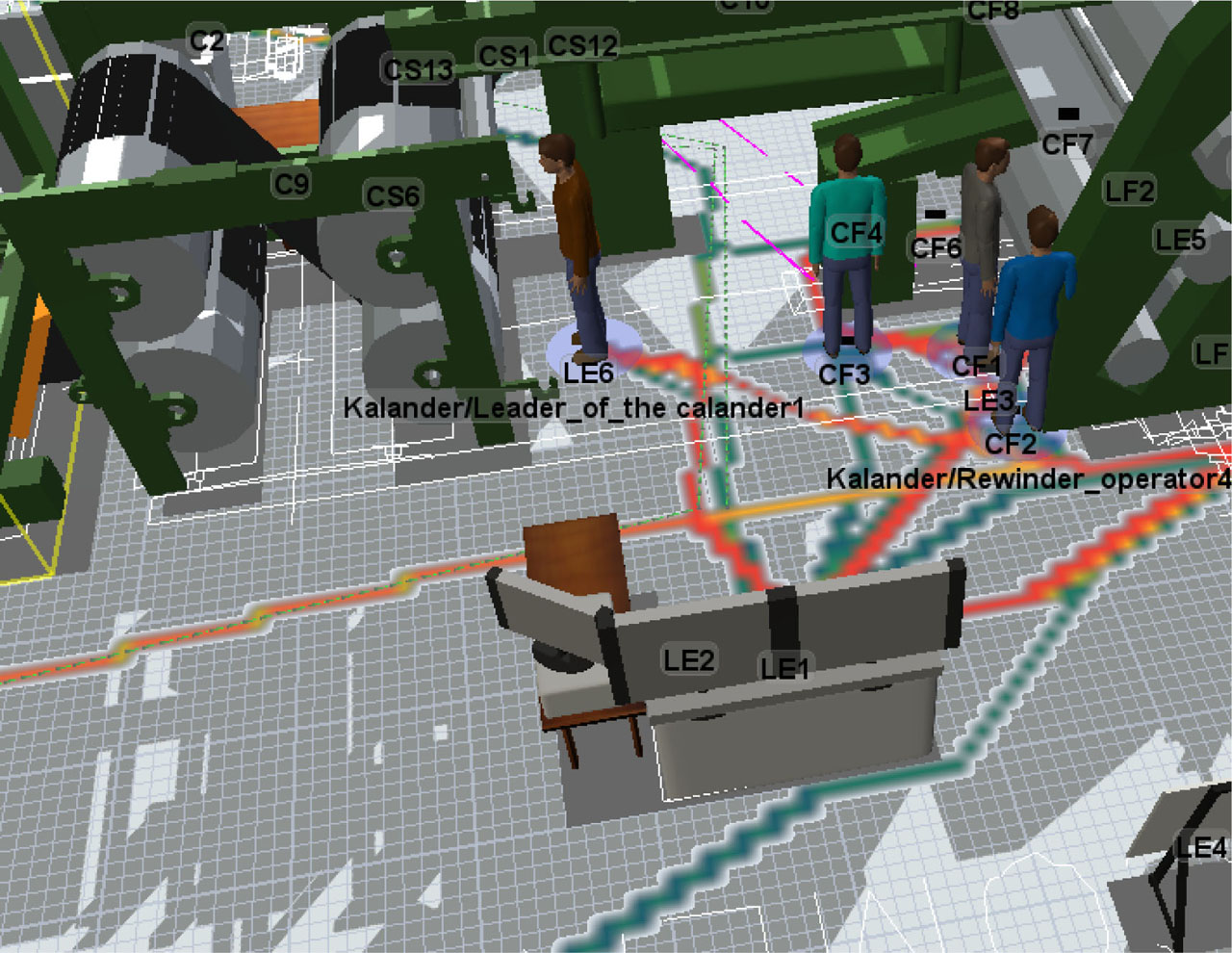
Figure 4
Example of path drawing (Source: Own study)
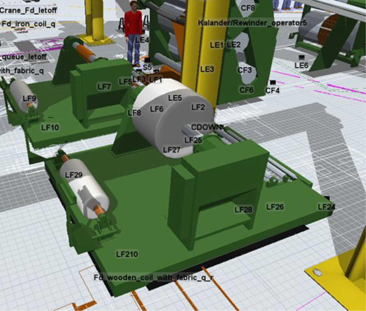
Figure 5
The two letoffs next to each other (Source: Own study)
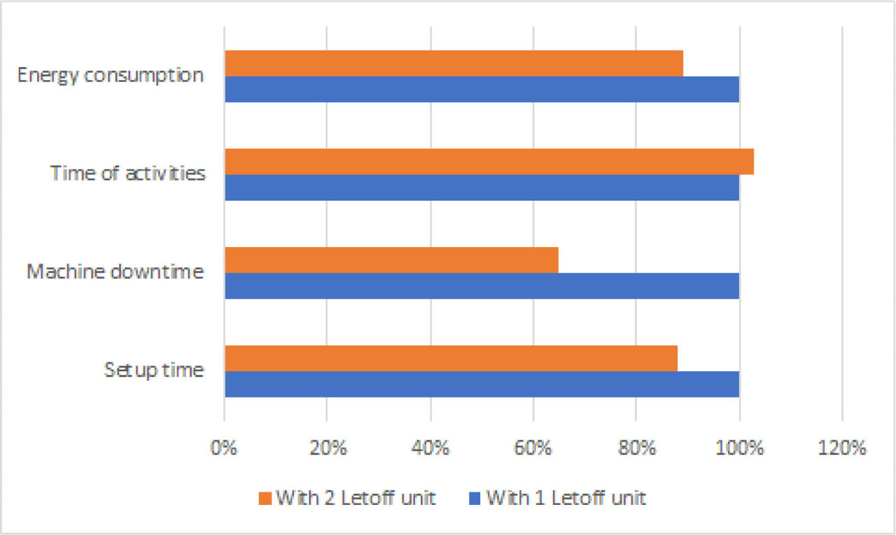
Figure 6
Results of the experiments (Source: Own study)
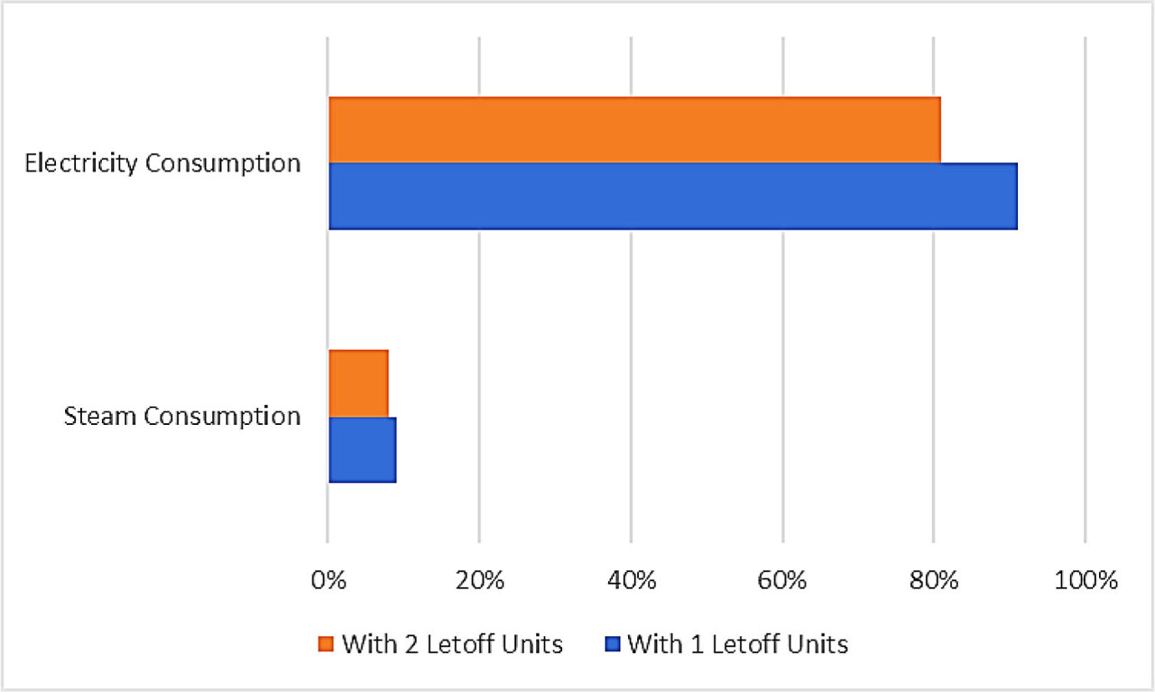
Figure 7
Electricity and steam savings (Source: Own study)

Figure 8
Gant diagram of setup times – one and two letoff units used (Source: Own study)
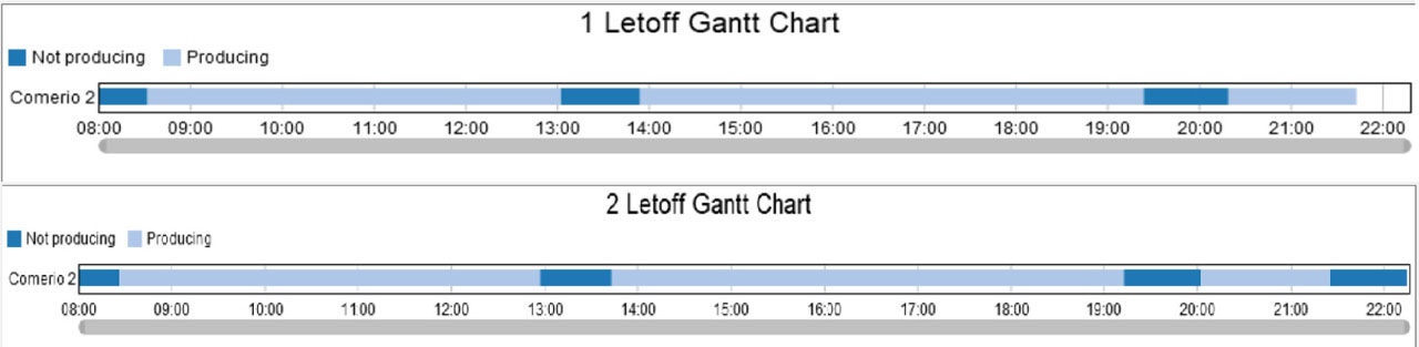
Figure 9
Gant diagram of machine downtime and process time with one and two letoff units used (Source: Own study)