
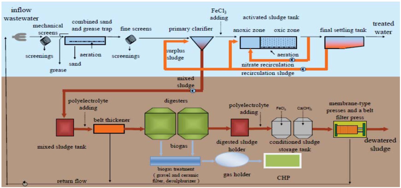
Figure 1
Process flow of the North Budapest WWTP. Besides the membrane-type presses and the belt filter press, industrial centrifuges largely complement the final dewatering process not shown on the illustration.
Table 1
Annual average composition of the incoming raw wastewater and the AD effluent from the centrifuges, as well as the discharge threshold defined by legislation for the North Budapest WWTP. COD: Chemical Oxygen Demand, TSS: total suspended solids, TNK: total Kjeldahl nitrogen, TP: total phosphorus. The legal threshold on the total nitrogen content (35 mg L-1) also includes the ammonium nitrogen concentration (*). All concentrations are in mg L-1.
| pH | COD | Filtered COD | TSS | N(NH3- NH4) | NO2- | NO3- | TNK | PO4-P | TP | |
|---|---|---|---|---|---|---|---|---|---|---|
| Incoming raw wastewater | ||||||||||
| mean | 7.7 | 575.8 | - | 313.7 | 55.3 | 0.49 | 1.5 | 71.4 | 15 | 10.4 |
| error (±2SD) | 0.55 | 427.9 | - | 301.4 | 30.6 | 1 | 3.4 | 33.5 | 11.4 | 7.8 |
| AD effluent | ||||||||||
| mean | 8.1 | 7572.9 | 675.3 | 7842.4 | 1376.1 | - | - | 1688.9 | 53.2 | 263.5 |
| error (±2SD) | 0.3 | 7801.1 | 347 | 8568.9 | 415.3 | - | - | 521.2 | 48.4 | 241.3 |
| Legal thresholds | ||||||||||
| 6.5-9.0 | 125 | 35 | 10 | 35* | 5 | |||||
Table 2
Different input sources used to feed the anaerobic digesters at North Budapest WWTP (2016).
| Type | Dry matter [tonnes/a] | Organic matter w/w% |
|---|---|---|
| Concentrated sludge from on-site | 17900 | 73 |
| Slaughterhouse waste | 2300 | 83 |
| Dewatered sludge from other WWTPs | 1000 | 69 |
| External liquid waste | 360 | 75 |
Table 3
Volume of the AD effluent in 2017 (first 11 months) processed by different techniques at the North Budapest WWTP.
| Thickening table (m3) | Centrifuge (m3) | Press (m3) | Belt press (m3) | Total (m3) | |
|---|---|---|---|---|---|
| Monthly average volume (m3) | 19 886.61 | 25 965.42 | 3 029.19 | 8 032.57 | 52 381.40 |
| error (±2SD) | ±6795.47 | ±9019.76 | ±1665.19 | ±11984.39 | ±9290.88 |
| Annual total volume (m3) | 218 752.73 | 285 619.61 | 33 321.04 | 32 130.29 | 576 195.38 |
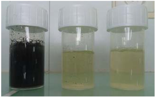
Figure 2
From left to right: untreated AD effluent, settled and filtered samples.
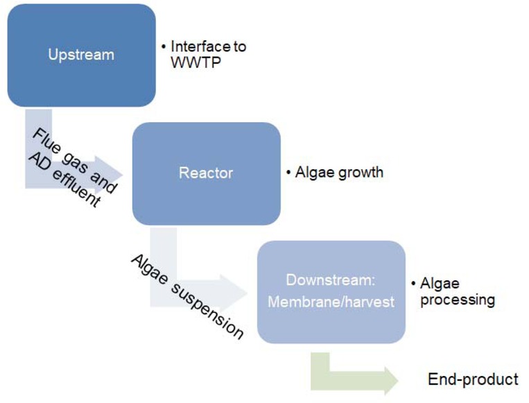
Figure 3
Flow chart of the technology integration including the three tailorable modules.
Table 4
Quality of pre-treated AD effluent and its difference between each batch. Data are shown in (mg L-1).
| May | June | July | August | |
|---|---|---|---|---|
| pH | 7.62 | 7.39 | 8.15 | 8.06 |
| COD | 615 | 1597 | 750 | 667 |
| TSS | 30 | 140 | 150 | 65 |
| total-P | 97 | 100 | 61 | 75 |
| dissolved-P | 68 | 56 | 58 | 36 |
| N(NH4-NH3+) | 683 | 622 | 930 | 872 |
| organic-N | 8 | 8 | 53 | 67 |
| nitrite-N | 0.010 | 0.036 | 0.041 | 0.023 |
| nitrate-N | 6.200 | 1.300 | 0.152 | 0.274 |
| Ca | 127 | 187 | 117 | 101 |
| Mg | 38 | 59 | 17 | 33 |
| Cu | 0.01 | 0.05 | 0.01 | 0.02 |
| Cd | 0.003 | 0.001 | 0.001 | 0.001 |
| Ni | 0.007 | 0.05 | 0.019 | 0.002 |
| Pb | 0.012 | 0.017 | 0.002 | 0.005 |
| Mo | 0.05 | 0.05 | 0.05 | 0.05 |
| As | 0.01 | 0.01 | 0.016 | 0.01 |
| Cr | 0.014 | 0.006 | 0.002 | 0.007 |
| Fe | 1.71 | 5.26 | 1.18 | 1.04 |
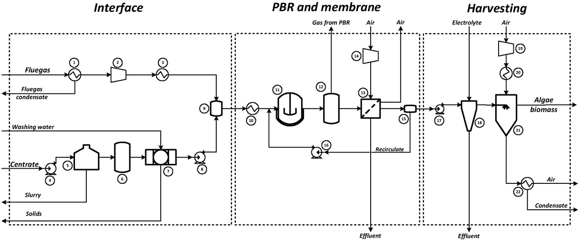
Figure 4
Simplified flowsheet diagram of the microalgae integration system. Major equipment list: 1. Heat exchanger, 2. Blower, 3. Heat Exchanger, 4. Pump, 5. Settler, 6. Buffer tank, 7. Sand filter, 8. Pump, 9. Mixer, 10. Heat exchanger, 11. Photobioreactor, 12. Degasing unit, 13. Membrane, 14. Blower, 15. Splitter, 16. Pump, 17. Pump, 18. Centrifuge, 19. Blower, 20. Heat Exchanger, 21. Dryer, 22. Heat Exchanger.
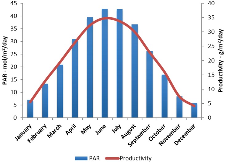
Figure 5
Average photosynthetically active radiation (PAR) data and algal productivity data for Budapest as used for the modelling.
Table 5
Settling time of the AD effluent used for growing microalgae at the case study location of the North Budapest WWTP.
| Month of refilling | Settling time (day) | Recovered clean AD effluent (m3) |
|---|---|---|
| April | 34 | 3 |
| May | 23 | 8 |
| June | 27 | 5 |
| August | 13 | 7 |
Table 6
Chemical analysis of the unknown precipitation, data in mg kg-1. TC: total carbon, TN: total nitrogen, TP: total phosphorus, TS: total sulfur.
| Precipitation | ||||||||||
|---|---|---|---|---|---|---|---|---|---|---|
| Na | B | Mn | TC | Zn | Ca | Cu | TN | TP | Mo | Hg |
| 1100 | 825 | 649 | 194800 | 142 | 208000 | 60.5 | 27550 | 103877 | 22.5 | 0.5 |
| Se | TS | K | Pb | Fe | Mg | As | Co | Ni | Cd | |
| 9.02 | 3880 | 0.36 | 4.6 | 6.06 | 4830 | 1 | 0.54 | 0.79 | 0.2 |
Table 7
Mass balance table. The results are calculated from the added AD effluent composition, current nutrient concentrations and in form of microalgae biomass (both harvested and remaining in the pond) as remaining biomass composition.
| Input in AD effluent | Current nutrient concentrations | In form of microalgae | Loss | |
|---|---|---|---|---|
| Nitrogen | 100% | 41% | 4% | 55% |
| Phosphorus | 100% | 22% | 40% | 38% |
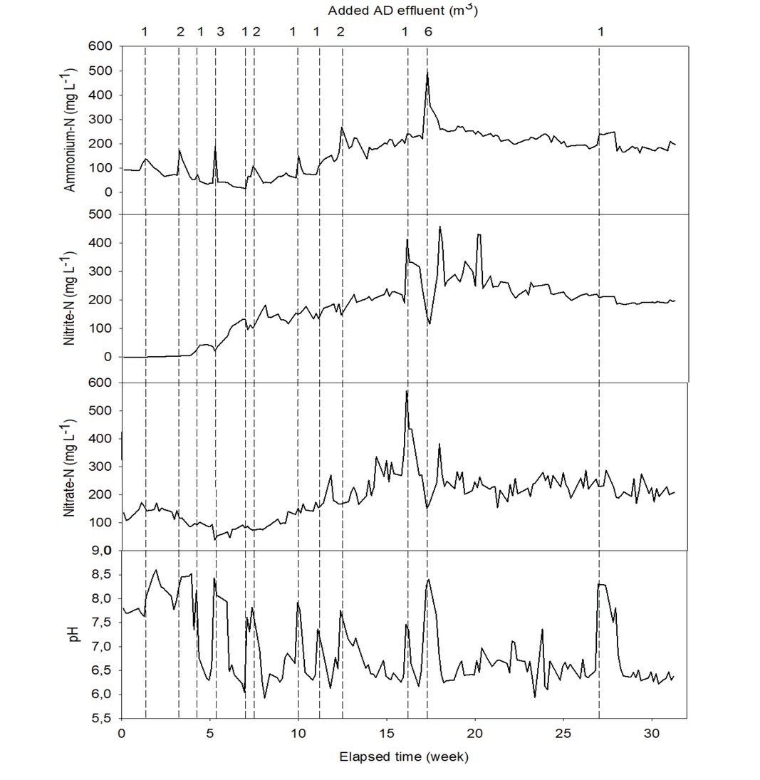
Figure 6
Changes of pH and nitrogen forms during operating of the open pond. Peaks in pH indicate the feeding of treated AD effluent (dashed vertical lines) which quickly falls due to ammonium loss and conversion. Peaks not marked are due to evaporation replenishing with tap water.
Table 8
Heavy metal content analysis from two different batches of the harvested microalgae biomass, and food contact material limit. The symbol (*) shows the concentration value is close to the limit and the symbol (**) means the value exceeds the limit.
| As μg kg-1 | Cd μg kg-1 | Co μg kg-1 | Cr μg kg-1 | Cu mg kg-1 | Mo μg kg-1 | |
|---|---|---|---|---|---|---|
| Batch 2 | 2674* | 52.1 | 567 | 4833 | 84.6** | 650* |
| Batch 3 | 1848 | 80.8 | 631 | 6072 | 38.5* | 1195** |
| Limit | 5000 | 500 | - | 50000 | 50 | 1000 |
| Ni μg kg-1 | Pb μg kg-1 | Zn mg kg-1 | F mg kg-1 | Se mg kg-1 | Hg mg kg-1 | |
| Batch 2 | 24986* | 2638 | 145* | 56.04* | 1.53** | 1.02** |
| Batch 3 | 2166 | 4306 | 255** | 184.4** | 1.02** | 1.02** |
| Limit | 25000 | 50000 | 150 | 100 | 0.75 | 0.5 |