
Table 1
The mathematical models of cigarette reported in the literatures.
| Reference and year | Author(s) | Smoking conditions | Geometry | Model construction | Simulation contents | ||
|---|---|---|---|---|---|---|---|
| Pyrolysis and char oxidation reaction kinetics | Transport system | Burning properties | Products | ||||
| (1) 1963 | Egerton et al. | Steady draw | 1-D | — | √ | Temperature | — |
| (2) 1966 | Gugan | Smoldering | 2-D | — | √ | Combustion cone Temperature | — |
| (3) 1977 | Baker | Smoldering | 1-D | — | √ | Heat release rate O2 concentration | CO, CO2 |
| (4) 1978 | Summerfield et al. | Steady draw | 1-D | Using the kinetics parameters obtained by themselves (4) | √ | Burning rate Temperature Pressure | — |
| (5,6,7) 1979–1981 | Muramatsu et al. | Smoldering | 1-D | Using the kinetics parameters obtained by themselves (5, 6) | √ | Burn rate Temperature Density | — |
| (8) 2001 | Miura et al. | Smoldering | 1-D | — | √ | Burning rate Temperature | — |
| (9) 2001 | Yi et al. | Smoldering | 2-D | Using the kinetics parameters obtained by Diblasi (10) | √ | Temperature Solid density Char density O2 concentration | Water |
| (11) 2002 | Chen | Smoldering | 1-D | Using the kinetics parameters obtained by themselves (11) | √ | Temperature Density | — |
| (12) 2003 | Rostami et al. | Smoldering | 2-D | Using the kinetics parameters reported by Muramatsu et al. (5, 6) | √ | Burning rate Temperature O2 concentration | — |
| (13) 2004 | Rostami et al. | Smoldering and steady draw | 2-D | Using the kinetics parameters reported by Muramatsu et al. (5, 6) | √ | Temperature O2 concentration Pressure Flow velocity | — |
| (14) 2004 | Saidi et al. | Puffing | 3-D | Using the kinetics parameters for volatile species reported by Wojtowicz et al. (15) | √ | Burning rate Temperature Flow velocity O2 concentration | CO, CO2 H2O Nicotine |
| (16) 2005 | Eitzinger et al. | Smoldering, puffing and steady draw | 2-D | Using the kinetics parameters obtained by themselves (16) | √ | Burning rate Temperature Flow velocity O2 concentration | Combustion gas Water |
| (17) 2007 | Saidi et al. | Puff-smoldering cycles | 3-D | Using the kinetics parameters for volatile species reported by Wojtowicz et al. (15) | √ | Burning rate Temperature Flow velocity O2 concentration Char density | CO, CO2 Volatile |
| (18) 2008 | Saidi et al. | Puff-smoldering cycles | 3-D | Using the kinetics parameters for volatile species reported by Wojtowicz et al. (15) | √ | Burning rate Temperature Flow velocity Char density | CO, CO2 H2O |
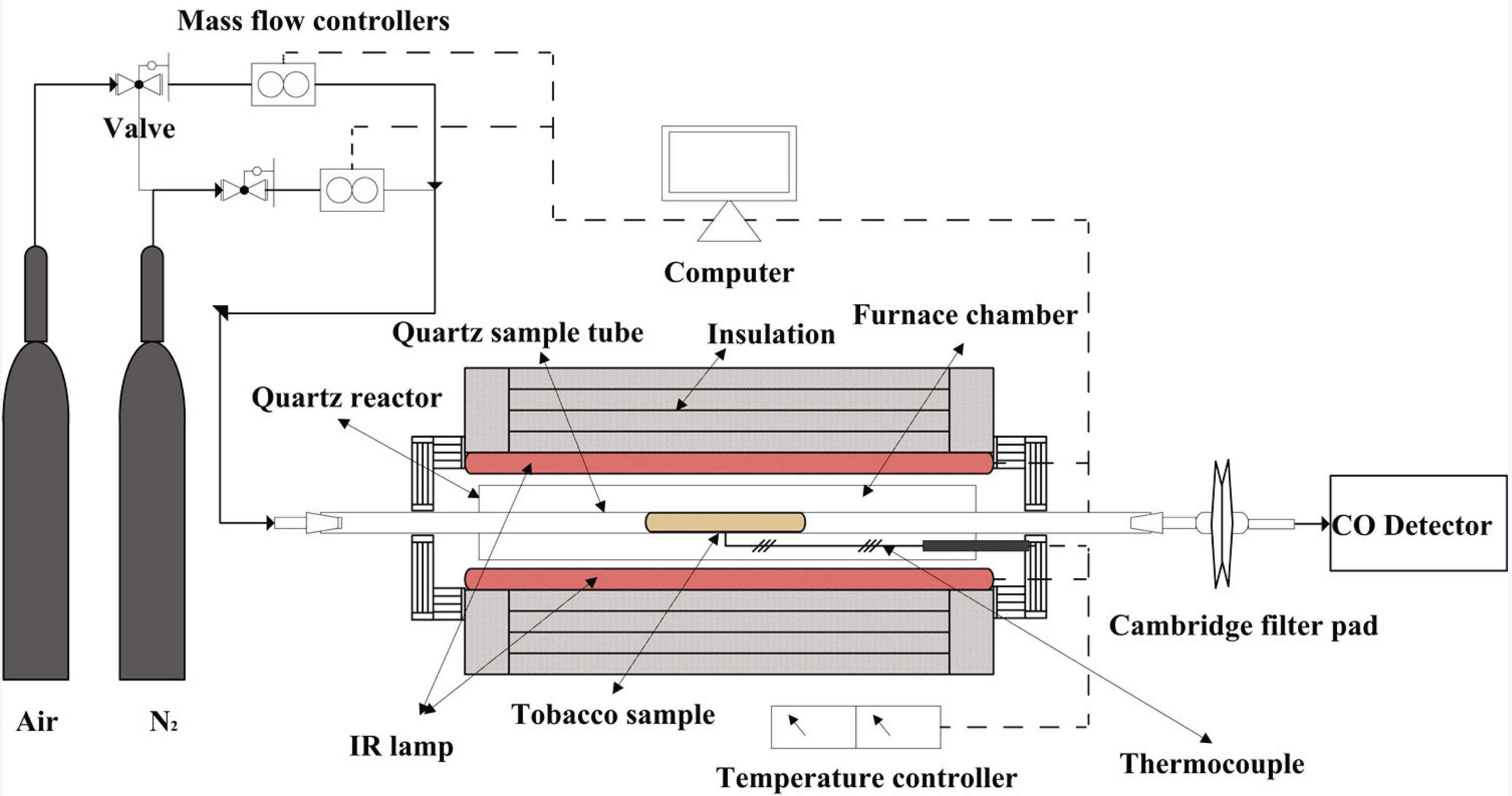
Figure 1
Schematic diagram of tobacco pyrolysis and combustion reaction system.
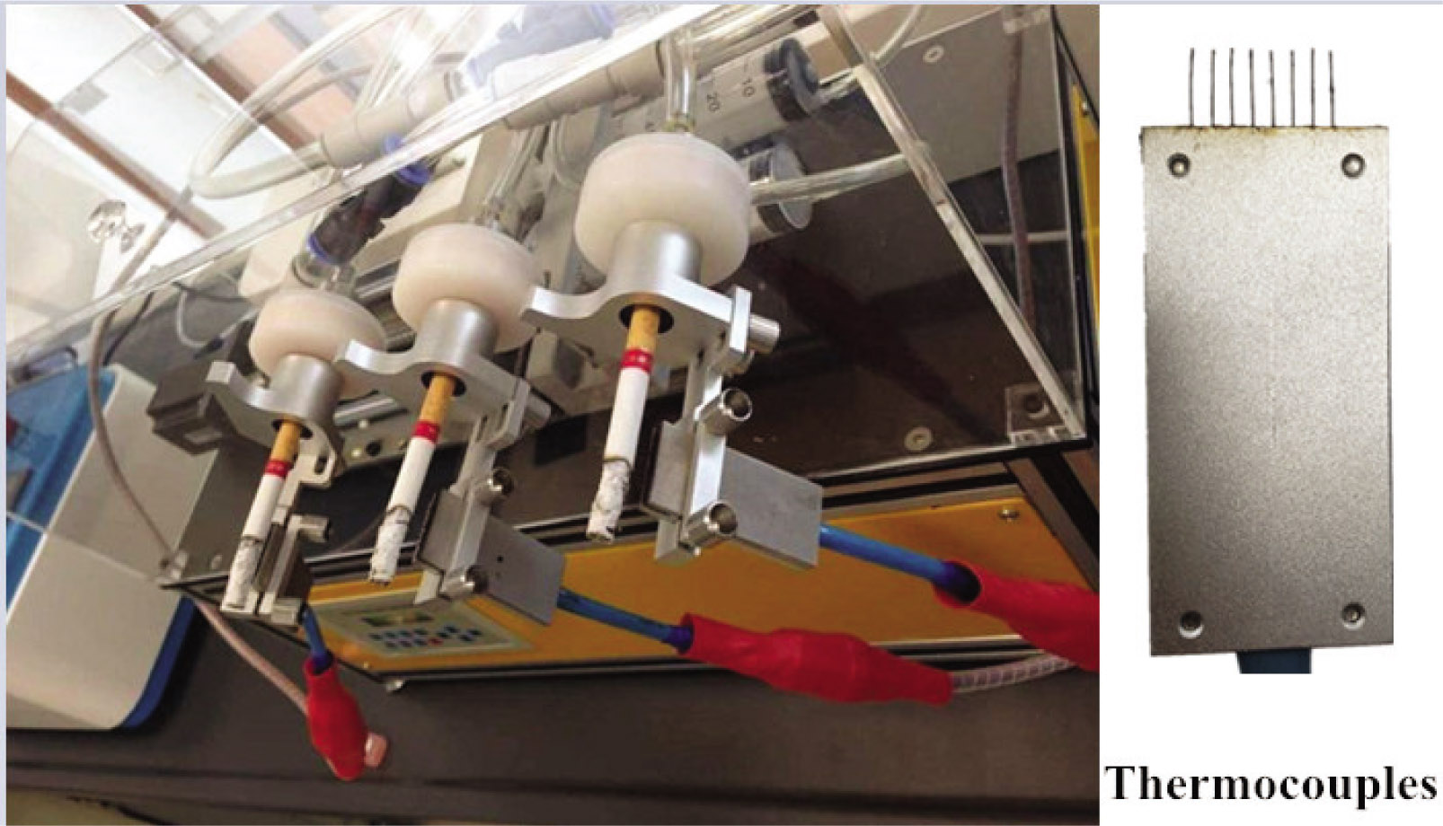
Figure 2
Gas temperature measurement system.
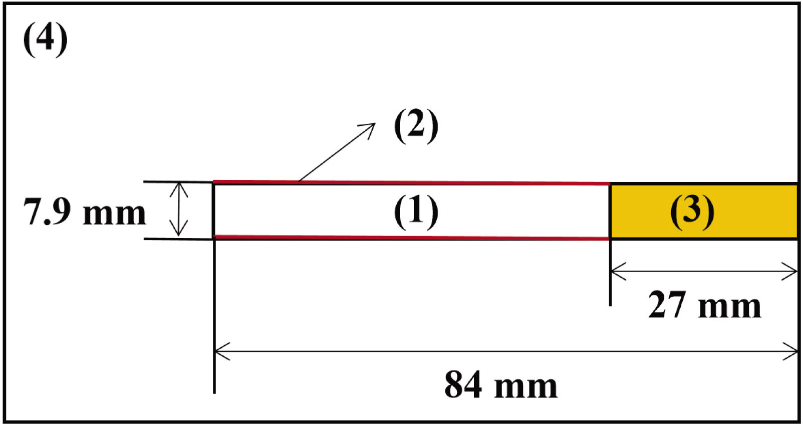
Figure 3
The geometry of the computational domains.
1) Tobacco rod; 2) Cigarette paper; 3) Filter rod; 4) External environment.
Table 2
Parameters and values related to each domain.
| Domain | Parameter | Definition | Unit | Value |
|---|---|---|---|---|
| 1) | ρs0 | Initial solid density | kg·m−3 | 740 (12) |
| ϕ | Porosity | 1 | 0.7 | |
| Cp,s | Specific heat of solid | kJ·kg−1·K−1 | 1.043 (12) | |
| Cp,g | Specific heat of gas | kJ·kg−1·K−1 | 1.004 (12) | |
| ks | Solid conductivity | W·m−1·K−1 | 0.316 (12) | |
| kg | Gas conductivity | W·m−1·K−1 | 0.0242 (12) | |
| ɛ | Emissivity of tobacco | 1 | 0.98 (12) | |
| dpore | Pore diameter | m | 5.75 × 10⁻⁴ (12) | |
| Hevaporation | Water evaporation heat | kJ·kg−1 | −2.2572 × 10³ (12) | |
| Hcombustion | Char combustion heat | kJ·kg−1 | 1.757 × 10⁴ (12) | |
| v | Flow velocity | m/s | 0 | |
| Kut | Permeability of unburned tobacco | m2 | 5.6 × 10⁻¹⁰ (18) | |
| Kbt | Permeability of burned tobacco | m2 | 105 (18) | |
| 2) | Kup | Permeability of unburned cigarette paper | m2 | 5 × 10⁻¹⁵ |
| Kbp | Permeability of burned cigarette paper | m2 | 105 (18) | |
| 3) | dp | Aerosol particle diameter | m | 4.4 × 10⁻⁷ (19) |
| df | Single fiber diameter | m | 2.51 × 10⁻⁵ (19) | |
| Dt | Total denier of filter | g·(9000 m)−1 | 35000 | |
| Ds | Denier of per single fiber | g·(9000 m)−1 | 3 | |
| Cfiber | Crimping ratio of fibers | 1 | 0.17 | |
| Sfilter | Cross-sectional area of filter rod | m2 | 4.899 × 10⁻⁵ | |
| Tfilter | Filter temperature | K | 288 | |
| Kfilter | Permeability of filter | m2 | 2.5 × 10⁻¹⁰ (18) | |
| 4) | T | Ambient temperature | K | 288 |
| P | Ambient gas pressure | kPa | 101.3 | |
| ρg0 | Initial gas density | kg·m−3 | 1.225 | |
| WO2 | Mass fraction of O2 | % | 23 | |
| WN | Mass fraction of N2 | % | 77 |
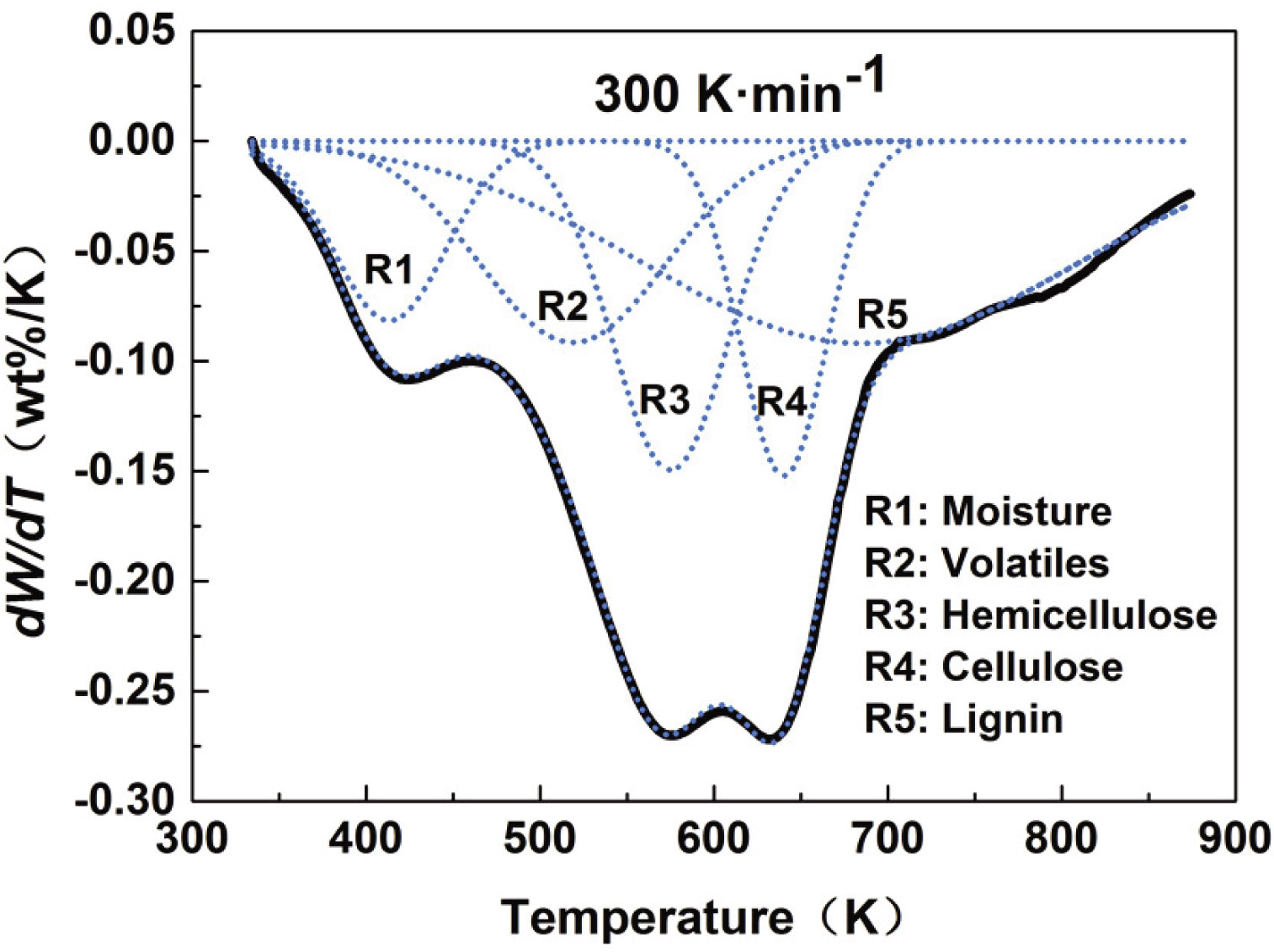
Figure 4
DTG of tobacco pyrolysis.
Table 3
Kinetic parameters of tobacco pyrolysis.
| Parameters | Unit | R1 | R2 | R3 | R4 | R5 |
|---|---|---|---|---|---|---|
| fp,j | % | 9.52 | 17.71 | 18.04 | 13.58 | 41.16 |
| Ap,j | min−1 | 1.47 × 10⁵ | 1.48 × 10⁸ | 1.82 × 10¹⁰ | 1.21 × 10¹³ | 0.4538 |
| Ep,j | kJ·mol−1 | 31.09 | 60.81 | 91.48 | 133.48 | 25.78 |
| np,j | — | 1.06 | 1.28 | 1.21 | 1.25 | 0.76 |
| mp,j | — | 1.24 | 1.54 | 1.48 | 1.49 | −0.04 |
| R2 = 0.9821 | ||||||
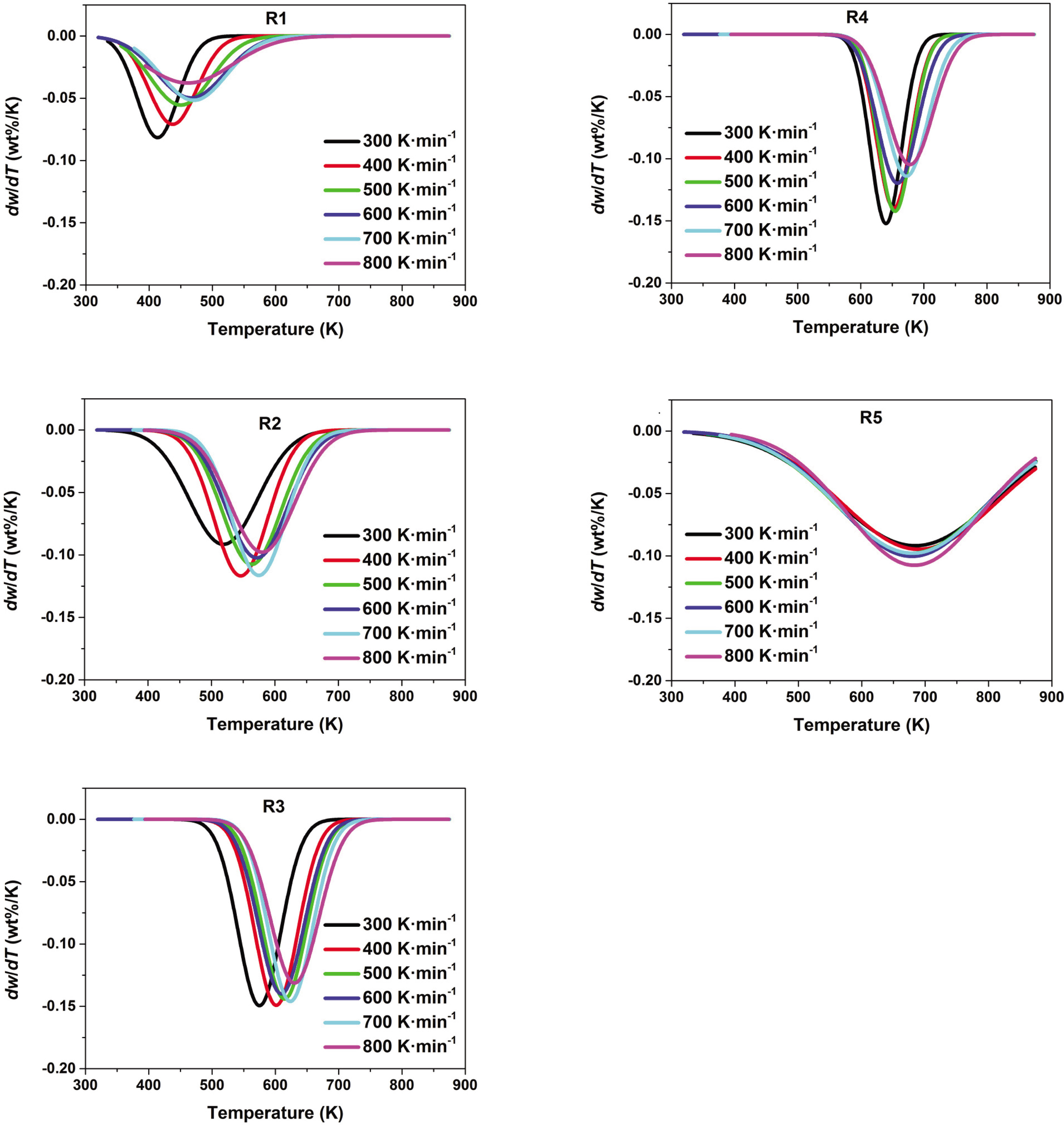
Figure 5
Approximated Gaussian peaks of five precursors at different heating rates.
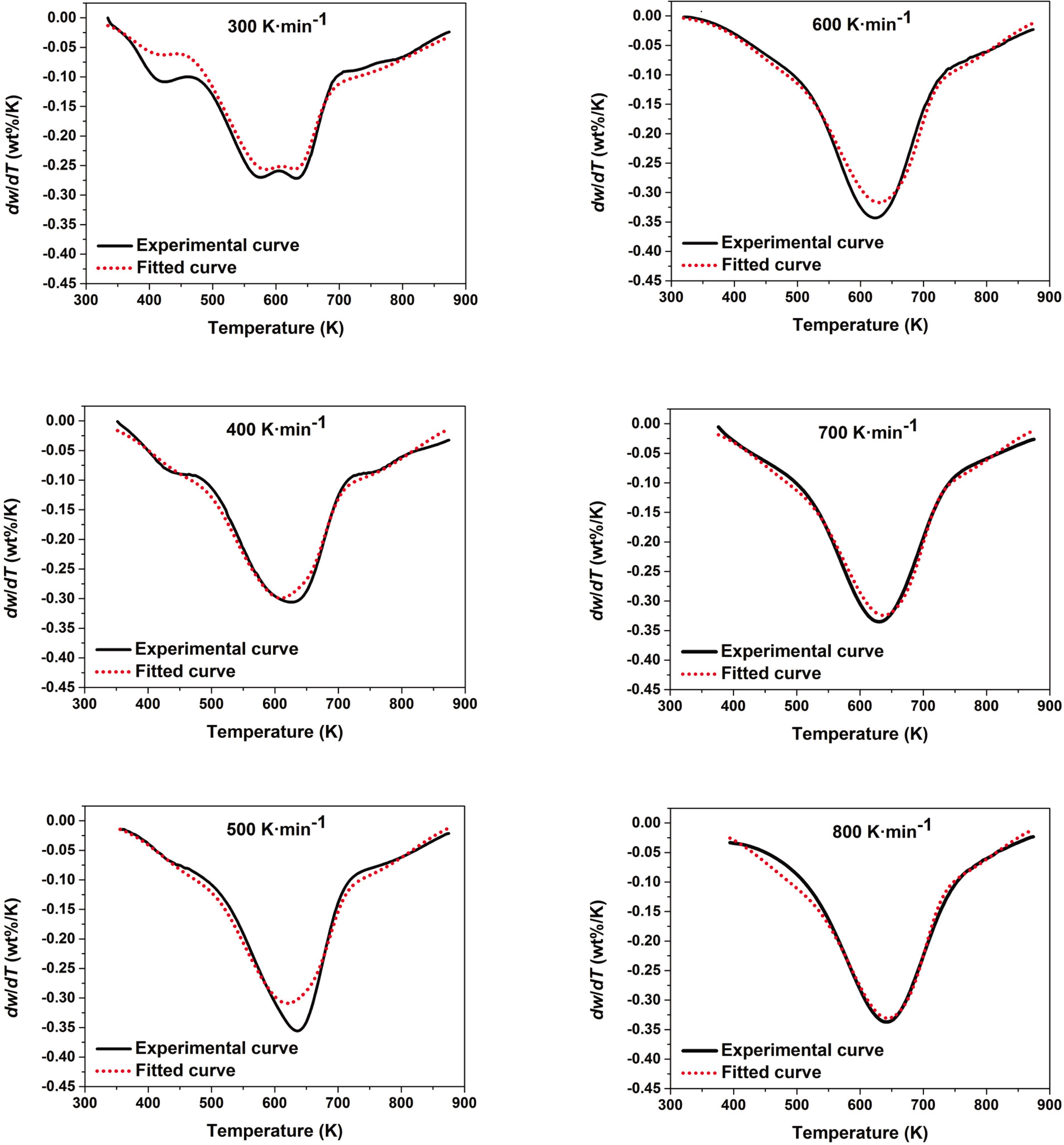
Figure 6
Comparison between the experimental DTG curves and the fitted DTG curves of the tobacco pyrolysis reaction at different heating rates.
Table 4
Kinetic parameters of char combustion.
| WO2 range | 0% ≤ WO2 ≤ 2% | 2 %< WO2 ≤ 10% | 10% < WO2 ≤ 23% | |
|---|---|---|---|---|
| Parameters | Unit | WO2 = 1%, 2% | WO2 = 3%, 5%, 10% | WO2 = 15%, 20% |
| Ac | min−1 | 1.48 × 10⁷ | 4.26 × 10⁷ | 8.30 × 10⁷ |
| Ec | kJ·mol−1 | 91.04 | 111.20 | 116.31 |
| no | — | 1.09 | 0.43 | 0.36 |
| R2 | 0.9441 | 0.9574 | 0.9537 | |
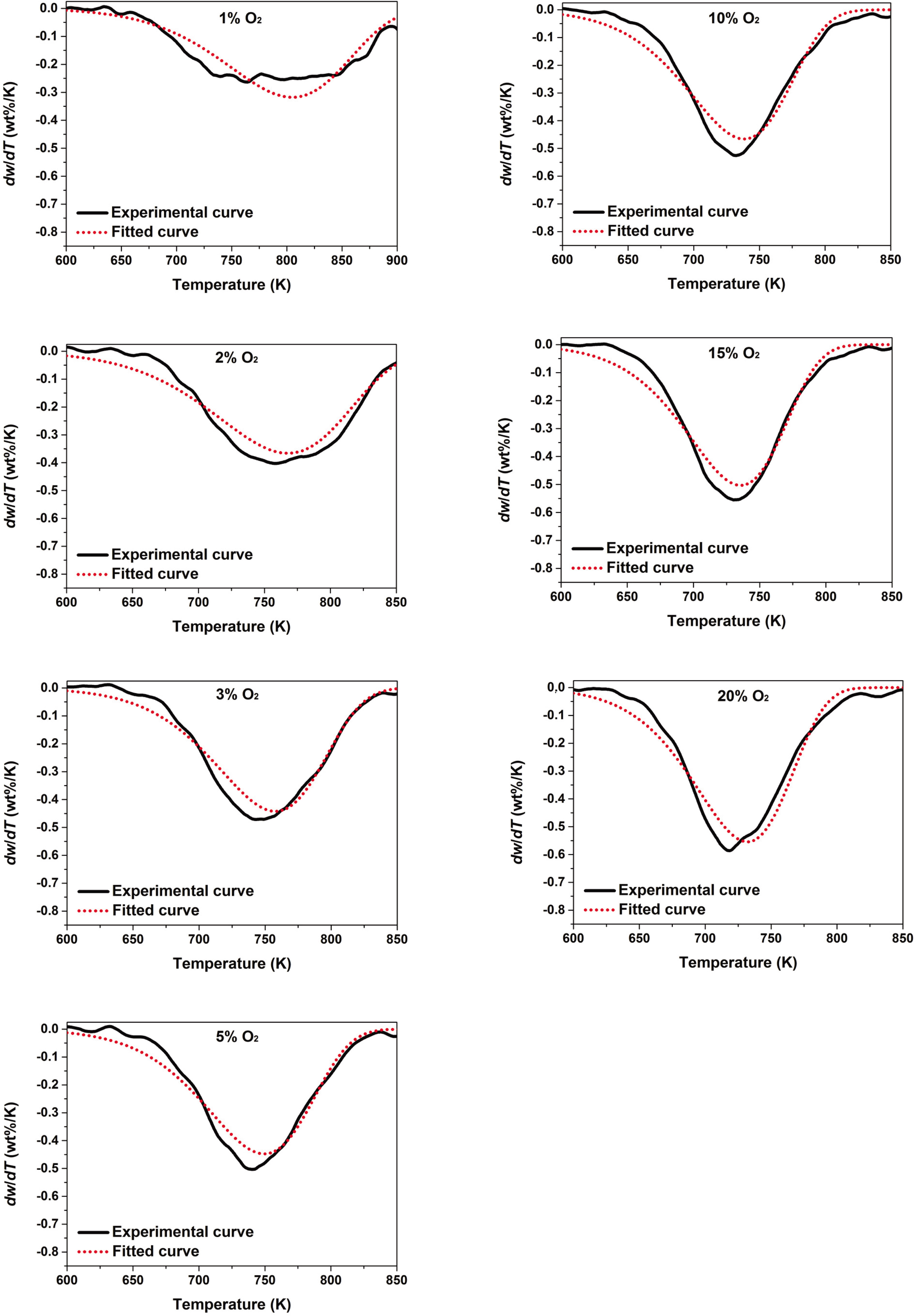
Figure 7
Comparison between the experimental DTG curves and the fitted DTG curves of char combustion at different oxygen concentrations.
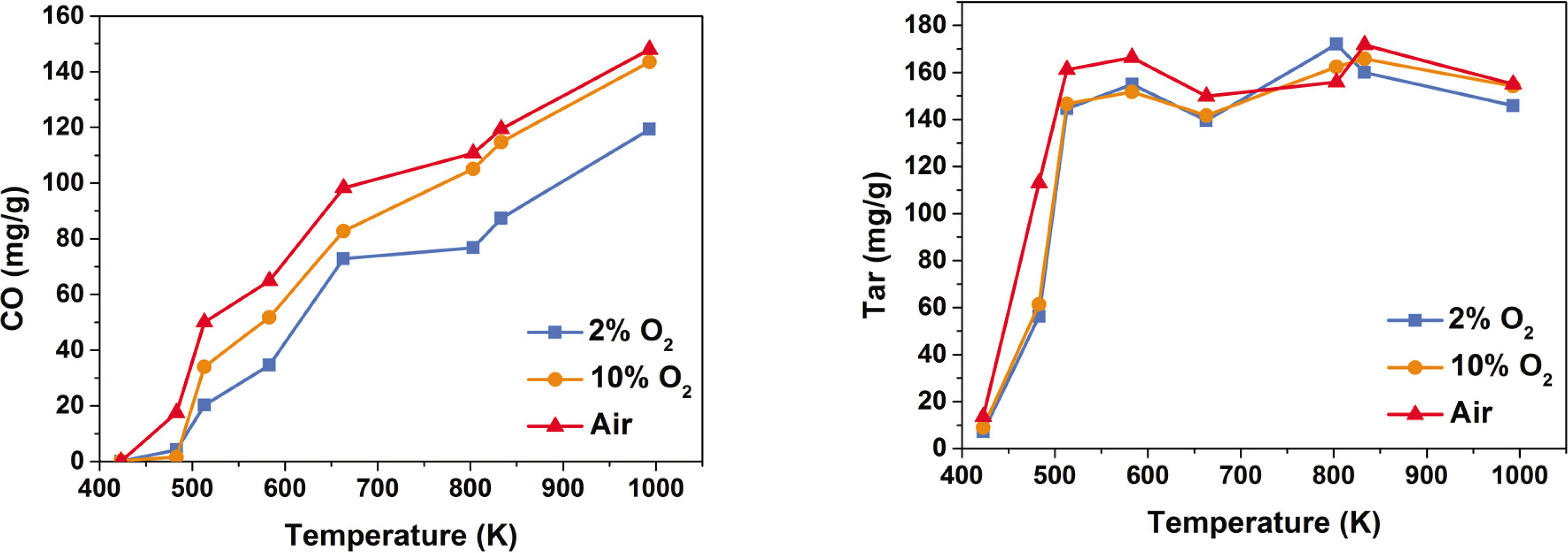
Figure 8
Release amounts of “tar” and co at different reaction conditions.
Table 5
Mathematical relationships of “tar” and CO at different temperatures and oxygen mass fractions.
| Temperature range | WO2 range | “Tar” (mg·g−1) |
| 423 K ≤ T ≤ 623 K | 0% ≤ WO2 < 5% | Y1 = −0.0049T2 + 5.8838T−1617 (R2 = 0.8990) |
| 5% ≤ WO2 < 15% | Y1 = −0.0048T2 + 5.7621T−1580 (R2 = 0.9034) | |
| 15% ≤ WO2 ≤ 23% | Y1 = −0.0061T2 + 7.1210T−1911 (R2 = 0.9734) | |
| 623 K T ≤ 1273 K | 0% ≤ WO2 ≤ 23% | 160 |
| Temperature range | WO2 range | CO (mg·g−1) |
| 423 K ≤ T ≤ 1273 K | 0% ≤ WO2 < 5% | Y2 = 0.2132T−89.19 (R2 = 0.9575) |
| 5% ≤ WO2 < 15% | Y2 = 0.2630T−107.32 (R2 = 0.9608) | |
| 15% ≤ WO2 ≤ 23% | Y2 = 0.2516T−90.41 (R2 = 0.9333) |
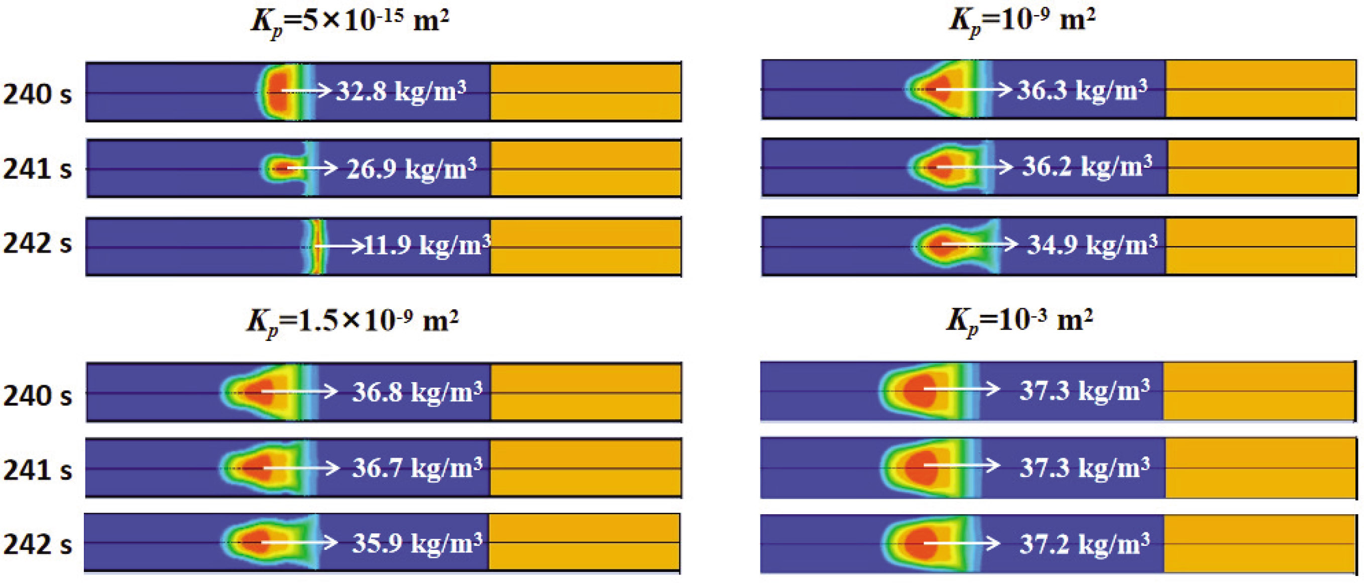
Figure 9
Density fields of char in four cases during puffing.
Table 6
Comparison of the numerical and experimental results.
| Case 1 | Case 2 | Case 3 | Case 4 | Experimental | ||
|---|---|---|---|---|---|---|
| “Tar” | (mg/cig) | 15.8 | 14.1 | 12.2 | 5.1 | 11.2 |
| Relative deviation | 41.1% | 25.9% | 8.9% | 54.5% | — | |
| CO | (mg/cig) | 21.1 | 17.3 | 14.6 | 5.6 | 13.2 |
| Relative deviation | 59.8% | 31.1% | 10.6% | 57.6% | — | |
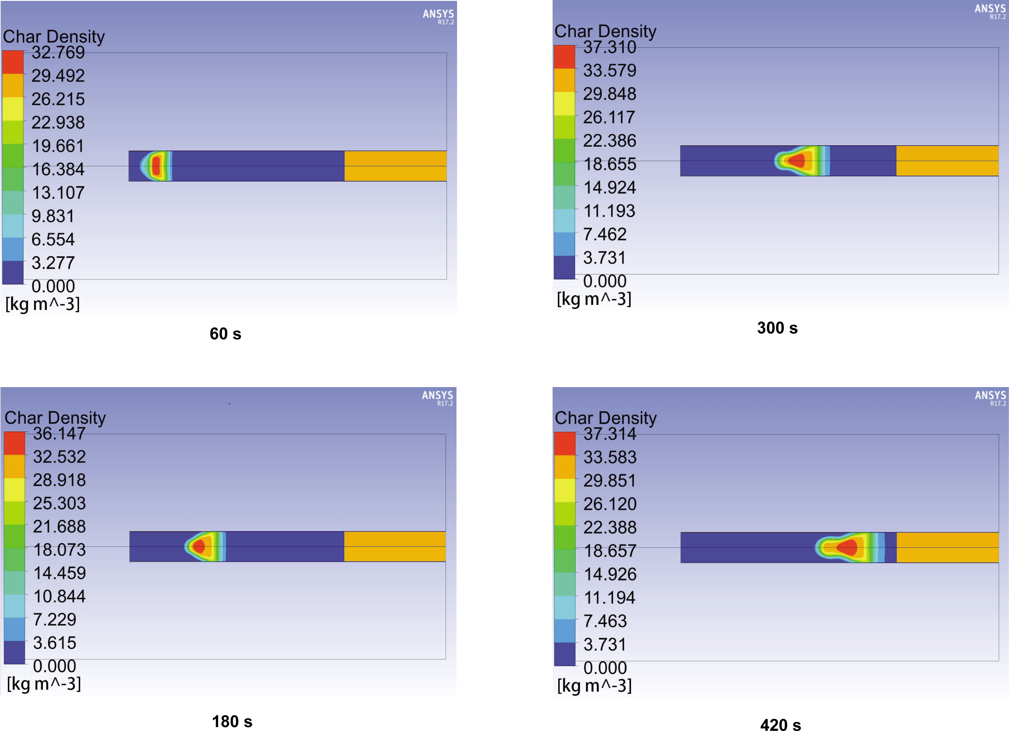
Figure 10
Density fields of char at different times (case 3).
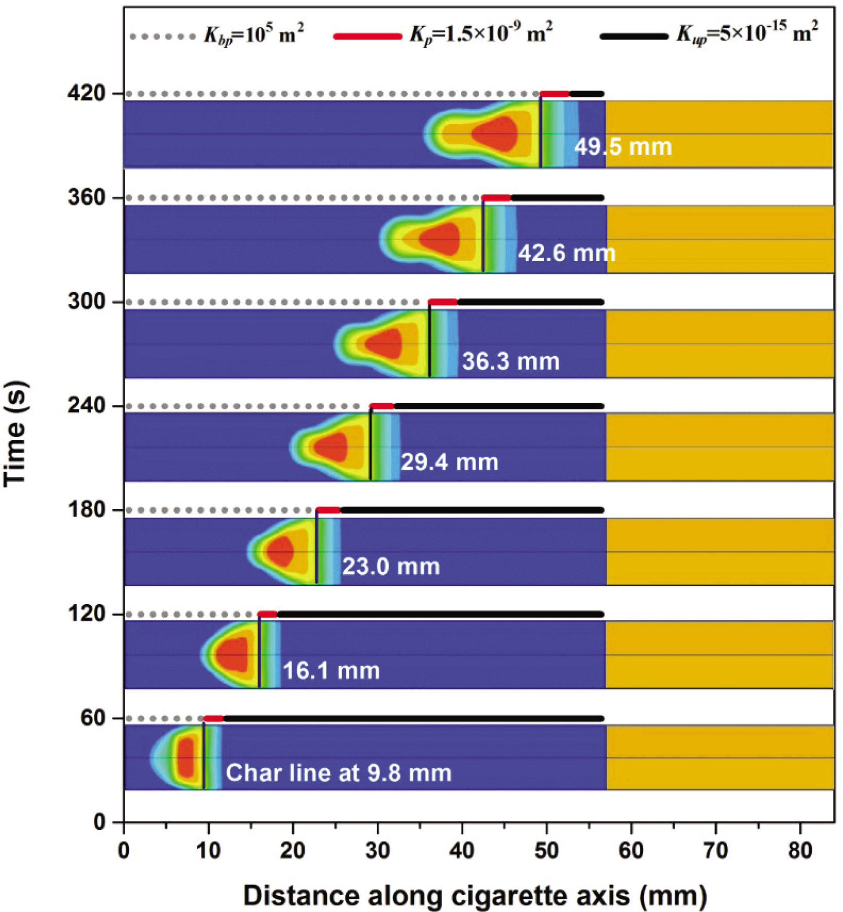
Figure 11
Permeability of the cigarette paper, char line and char density along the axis of the cigarette at different times (case 3).
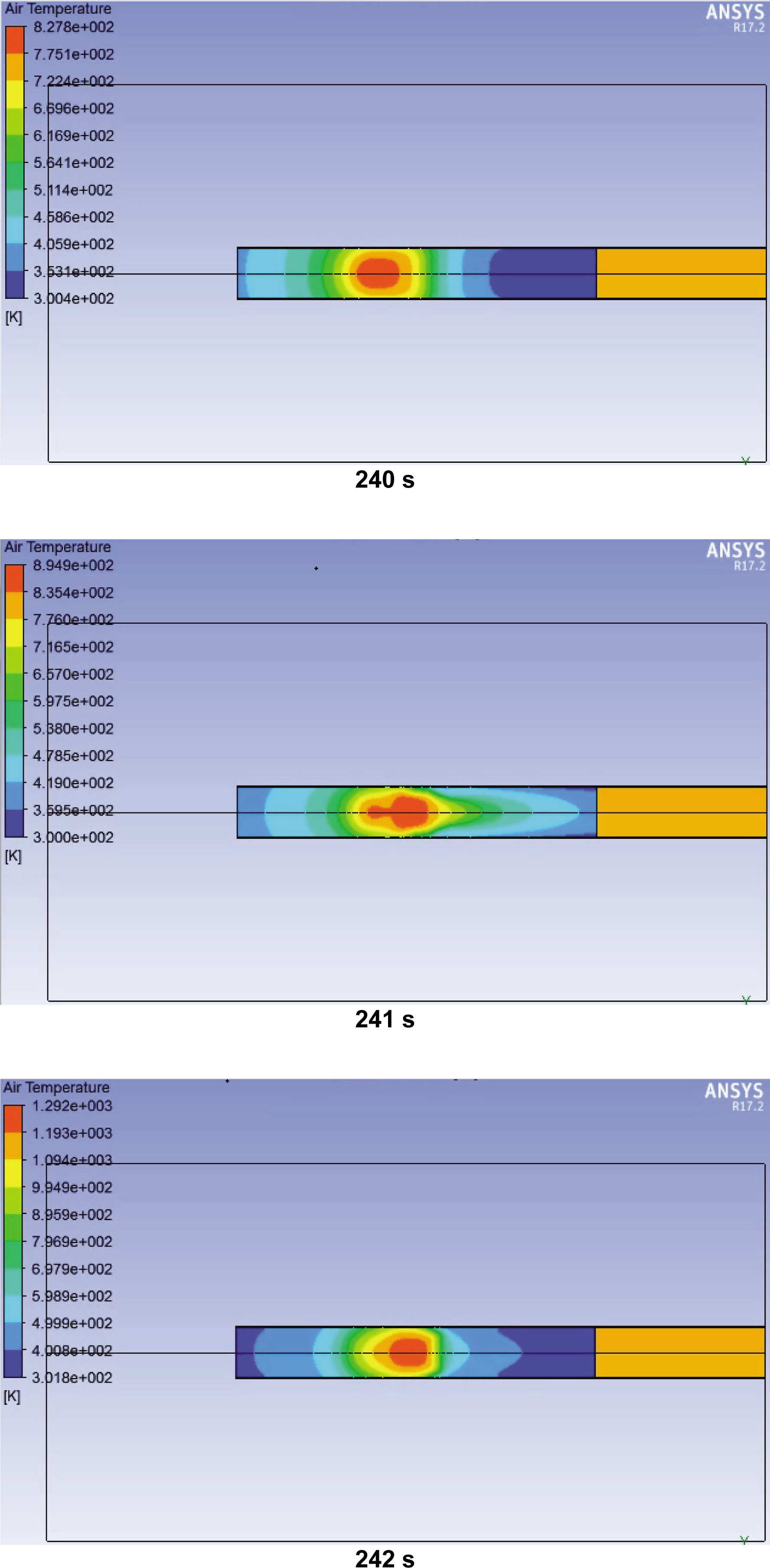
Figure 12
Gas temperature fields of cigarette during puffing (case 3).
Table 7
NRMSE of the predicted gas temperatures and experimental gas temperatures for eight locations.
| Location | 22 mm | 24 mm | 26 mm | 28 mm | 30 mm | 32 mm | 34 mm | 36 mm |
|---|---|---|---|---|---|---|---|---|
| NRMSE | 16.0% | 17.5% | 11.0% | 8.5% | 13.9% | 16.0% | 15.8% | 11.9% |
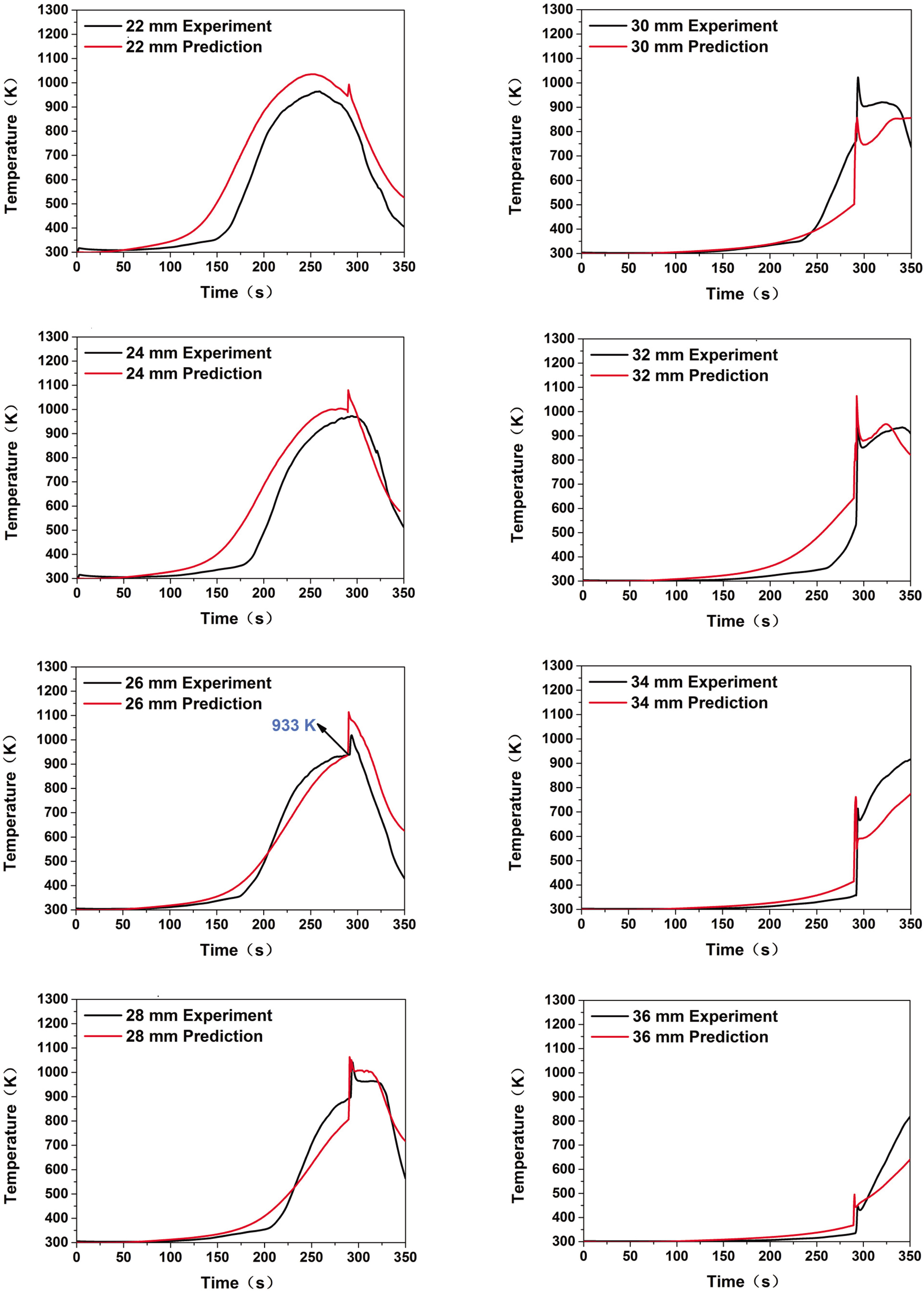
Figure 13
Comparison of experimental gas temperatures and predicted gas temperatures at different positions of a cigarette.
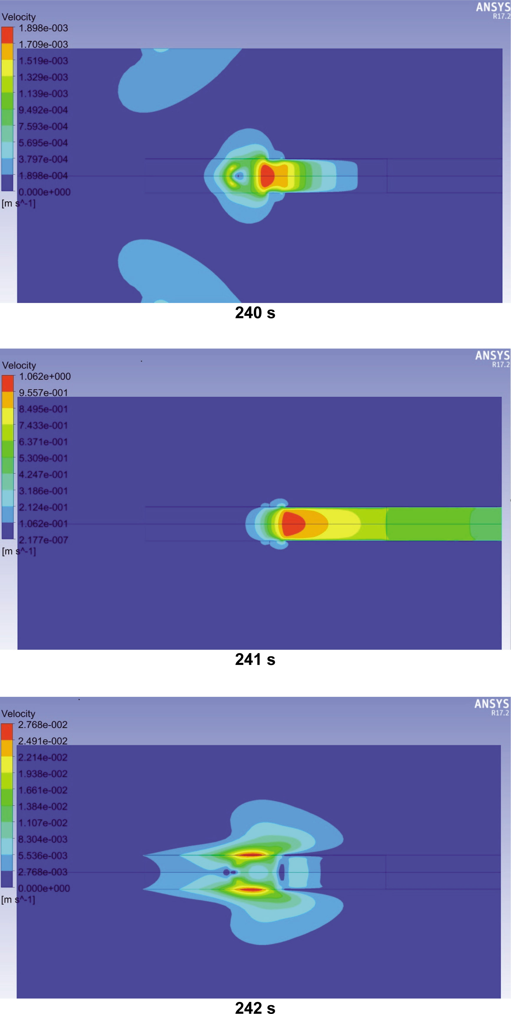
Figure 14
Flow velocity fields of cigarette during puffing (case 3).
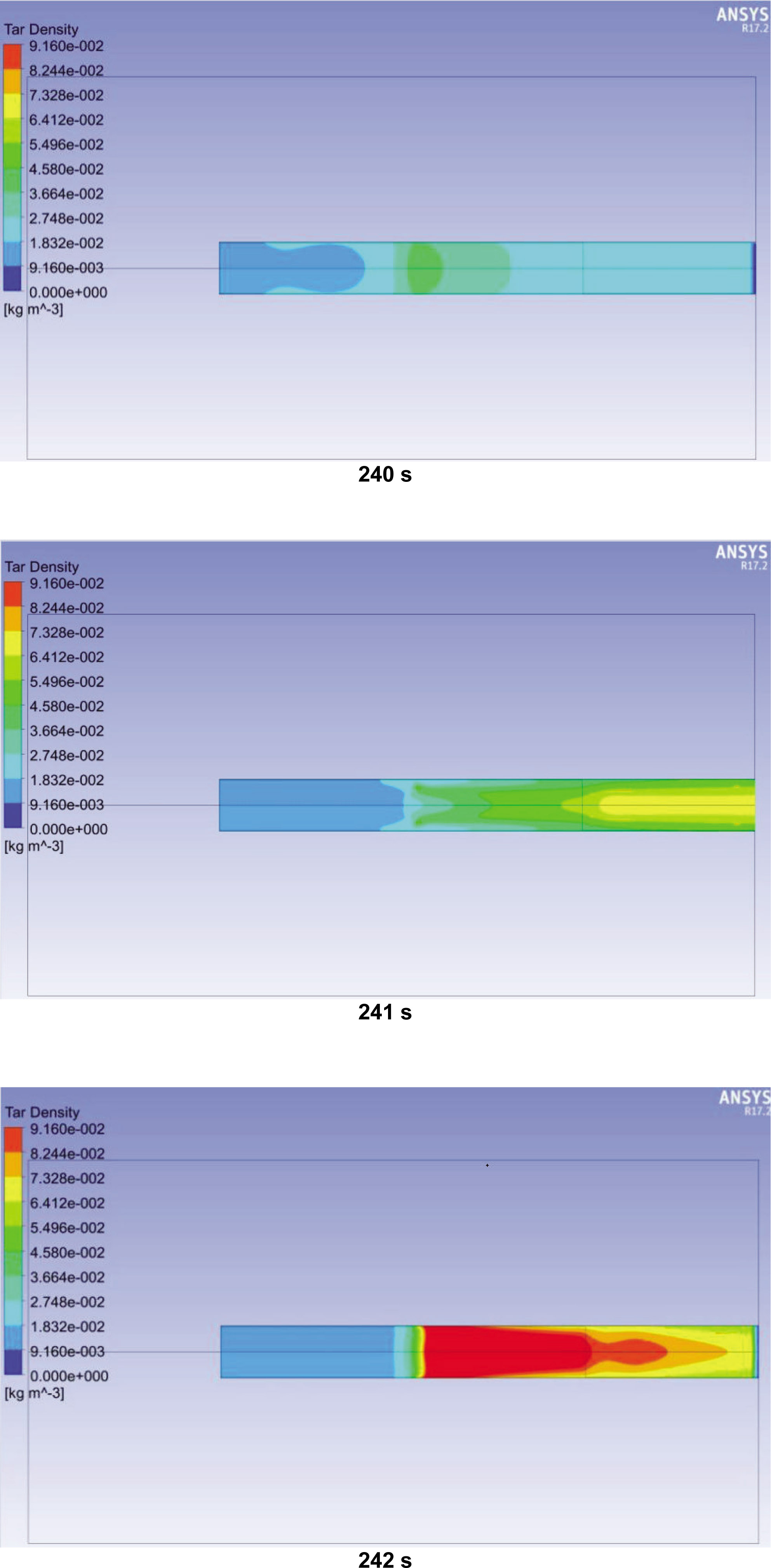
Figure 15
“Tar” density fields during puffing (case 3).
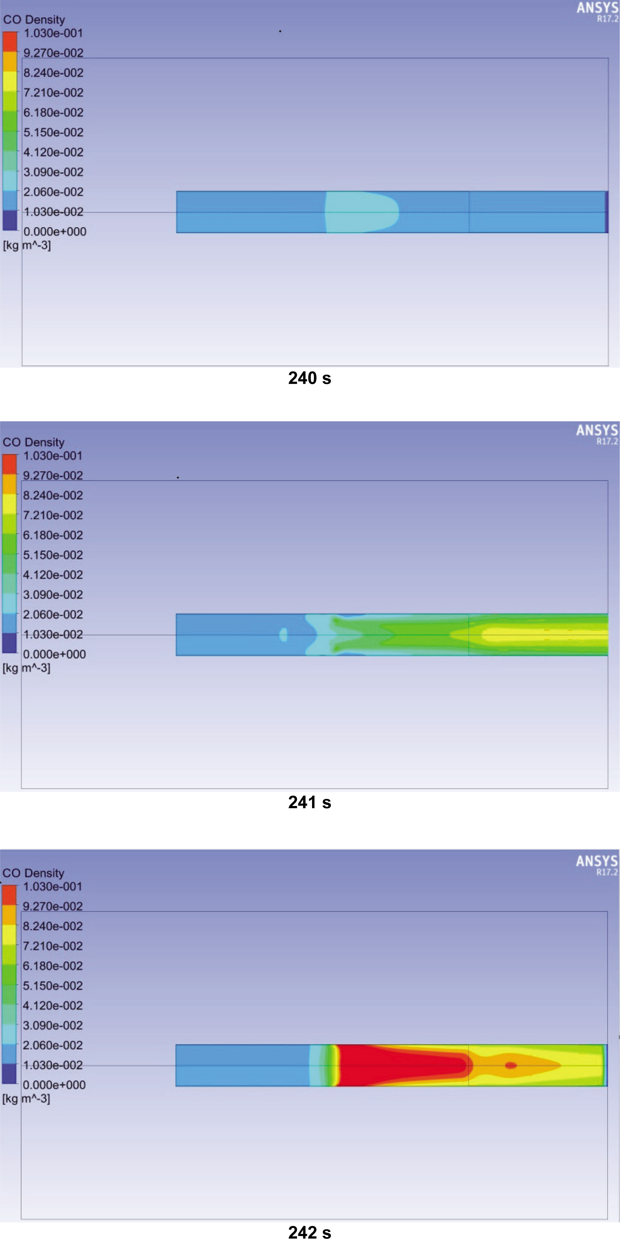
Figure 16
CO density fields during puffing (case 3).
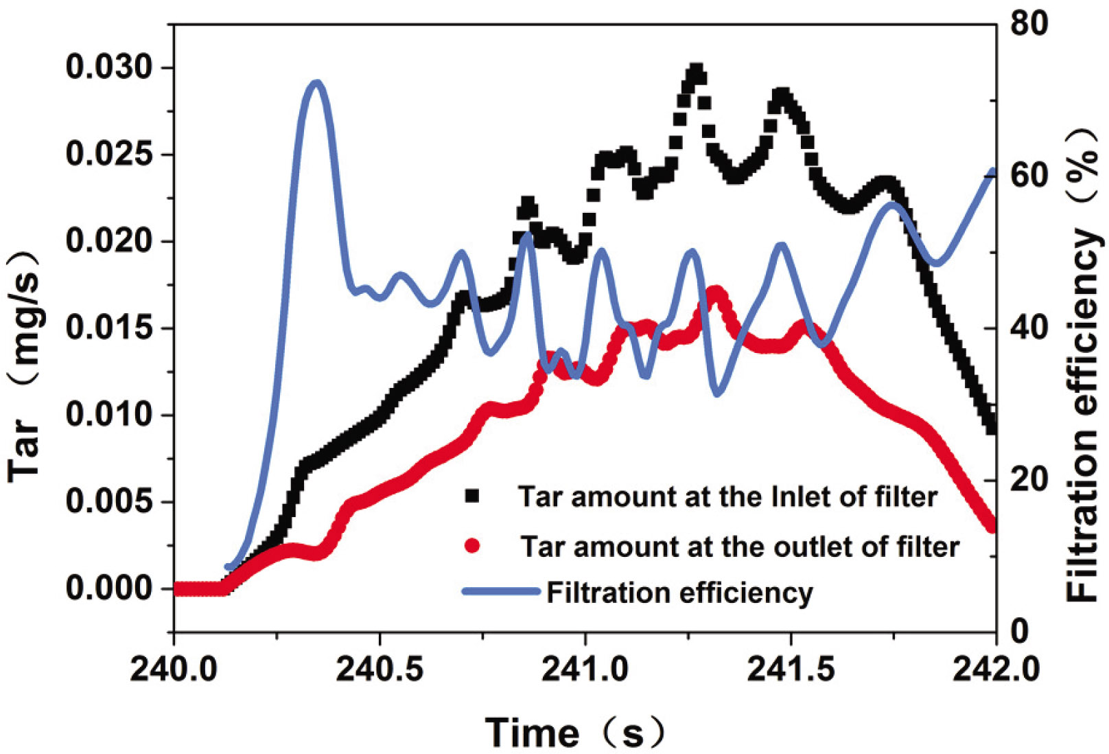
Figure 17
Released amounts of “tar” at the inlet and outlet of the filter rod and the filtration efficiency during puffing (case 3).
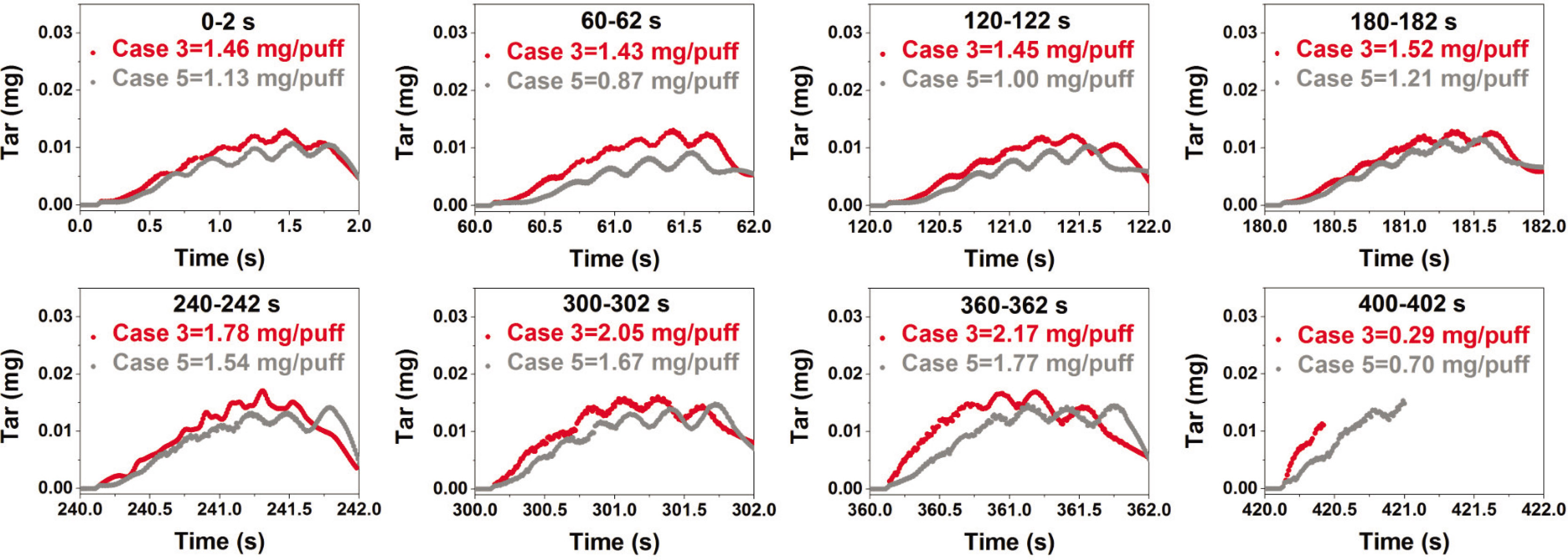
Figure 18
The puff-by-puff amounts of “tar” released in cases 3 and 5.
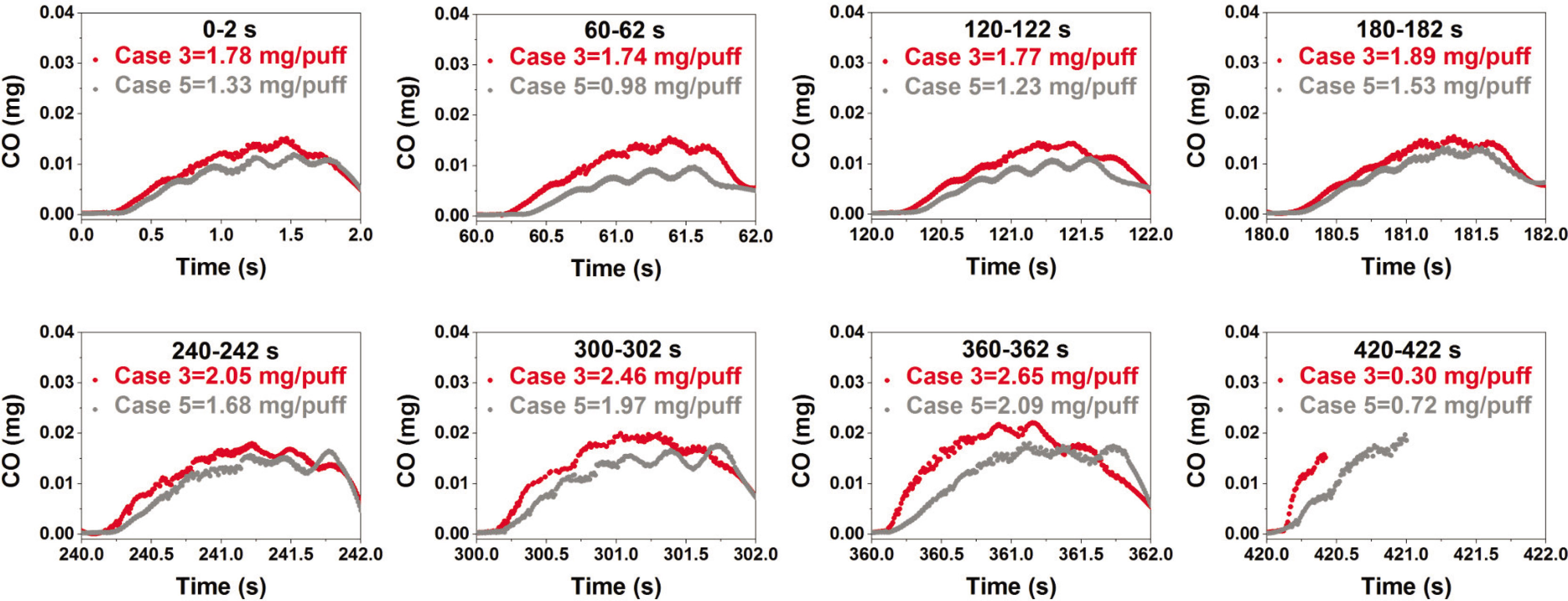
Figure 19
The puff-by-puff amounts of CO released in cases 3 and 5.