

Prestressed concrete is one of the most important construction technologies, which has had a significant impact on the development of bridge construction and other areas. It utilizes the advantages of concrete itself, specifically its compressive strength, in combination with high tensile strength of prestressing steel thereby significantly increasing the ultimate strength of structure. By applying compressive force to the concrete through prestressing tendons, a compressive reserve is created in areas subject to tensile stressed under loading, which also helps to reduce deformations and crack formation, this is described and illustrated in more detail in chapter 2. An example of this is the additional strengthening of an existing bridge structure using external (unbonded) prestressing steel, which, according to some studies (Naaman & Alkhairi, 1991), can increase the load capacity by several times compared to the original design. However, prestressed concrete structures must meet not only the ultimate limit state (ULS) requirements-preventing collapse due to loss of load capacity, but also the serviceability limit state (SLS), which governs criteria such as deflections and crack widths, ensuring the structure remains safe and functional throughout its service life.
From the structural behavior perspective, two fundamental types of prestressing steel are distinguished: bonded and unbonded, as illustrated in Figure 1. In the case of bonded tendons, the strands are placed within ducts embedded in concrete cross-section. After prestressing, these ducts are injected with grout, establishing a bond between the prestressing steel and the surrounding concrete. Force transfer occurs through adhesion and bond, and the strain in the tendons equals the strain in the adjacent concrete. In contrast, unbonded prestressing steel is not connected to the surrounding concrete in any way. The transfer of force from the tendons to the structure occurs through anchors and saddles. A typical example of this system is the use of monostrands – prestressing steel encased in HDPE sheathing filled with grease, routed either within or outside the concrete cross-section. This difference between bonded and unbonded tendons has a significant impact on structural behavior. While bonded tendons respond to local deformations of the cross-section, the stress in unbonded tendons is influenced by the global deformation of the entire structure. As a result, stress in unbonded tendons is redistributed based on the overall deflection and displacement of the structure, rather than local changes in cross-sectional strain (Alkhairi & Naaman, 1993; Virlogeux, 1989).
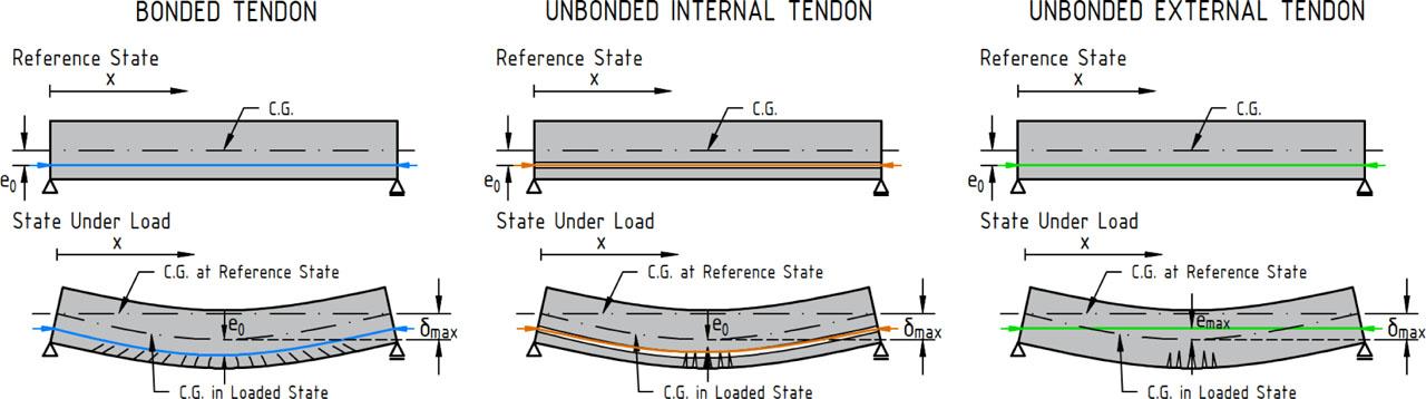
Type of prestressing tendon and their behavior under load
As shown in Figure 1, in the case of bonded tendons, the cable follows the deformation of the beam, and its eccentricity relative to the cross-section remains unchanged. In contrast, for unbonded tendons, the deformation of the beam causes a relative displacement of the tendon relative to the structure, which alters the eccentricity relative to the cross-section and consequently changed the internal force distribution (Naaman & Alkhairi, 1991).
Unbonded tendons are used in two main variants, and for both it is essential that there is no bond between the tendon and the surrounding concrete (the strain in the tendon and in the surrounding concrete are not equal during loading).
- ○
Internal unbonded tendons are placed inside the concrete cross-section but without any bond to the surrounding concrete. There is no direct structural connection between the prestressing tendon and the concrete. Since the tendon is placed inside the concrete, its profile is clearly defined. However, the effects on the structure during loading can still change, as the lack of bond means the effects depend on the global deformation of the structure. During loading, stress in the tendon increases only when the cable length between the anchorage’s changes, i.e., because of the overall deflection of the structure. The structural behavior of the prestressing tendon is more like that of external prestressing, for example in terms of limiting crack formation (the tendon does not restrain cracking to the same extent as bonded prestressing steel).
- ○
External unbonded tendons are located outside the concrete cross-section. The tendons are anchored in anchorage area and their profile is either straight or polygonal, with deviations occurring through saddles. Between these points, the tendon profile is straight. During loading, the geometry of the prestressing tendon changes relative to the structure. Only at the contact points between the tendon and the concrete (at saddles and anchorages) the geometry remains fixed relative to the cross-section. At these points, radial forces act on the structure. These forces beneficially contribute to the bending moment redistribution but also cause friction between the tendon and the saddle and generate local pressures that may lead to wear of both the tendon and its protective sheathing. External prestressing is used for strengthening existing bridge structures very often.
The serviceability limit state (SLS) is particularly important in the design of unbonded prestressing systems, as it includes requirements to limit deflections, stresses, crack widths, and to ensure the integrity of the corrosion protection system. Unlike conventional reinforced concrete structures, the strengthening of existing bridges with prestressing tendons is governed by serviceability considerations often, with the primary goal being to prevent the initiation or propagation of cracks and keep deflections within acceptable limits throughout the structure’s service life (Harajli, 1993). This is especially relevant for unbonded prestressing systems, there the lack of bond between tendon and concrete can lead to increasing local deformations and wider cracks. The following sections discuss the specific behavioral differences of unbonded tendons and their implications for serviceability, known issues identified in the literature, and include a case example of HDPE sheath thinning at small-radius saddle. Finally, recommendations are provided for the design of structures with unbonded prestressing systems in terms of the serviceability limit state.
The analytical approach to structures with unbonded prestressing tendons differs significantly from that used for bonded systems. Since the strain in the prestressing tendons and the surrounding concrete varies along the length, each increment in tendon strain depends on the global deformation of the structure under load, rather than the local strain in the concrete, as illustrated in Figure 2. In a simply supported beam with unbonded prestressing steel, the increase in tendon stress is not directly proportional to mid-span deformation. Instead, stress is redistributed based on the total change in tendon length caused by the overall deflection of the structure, as the tendons respond to the global deformation of the beam. As a result, unbonded tendons experience a smaller increase in prestressing force compared to bonded tendons under the same load, particularly during the initial stages of loading. Consequently, beams with unbonded tendons exhibit larger deformations upon cracking than their bonded counterparts, since the stress in the tendons increases more slowly than the tensile stress in extreme concrete fibers. With increasing beam deformation, the effective geometry of the unbonded tendon changes, which alters the internal force distribution. Therefore, the design must account for secondary moments caused by the variation in tendon shape (for instance, by introducing equivalent forces at saddles and anchorage zones) or the entire structure should be analyzed using a nonlinear approach (Alkhairi & Naaman, 1993).

Strain redistribution of general cross-section with bonded/unbonded prestressing steel (Alqam et al., 2021)
The stress in bonded prestressing tendon varies along their length due to prestress losses. In areas where crack form, the bonded tendons directly contribute to tensile force transfer because of their bond with the surrounding concrete. In contrast, unbonded tendons are not connected to concrete in any way, so after cracking, tensile forces cannot be smoothly transferred from the concrete into the tendons. Once cracks appear, the stress tends to concentrate in one or a few cracks, which may open significantly. In bonded systems, by comparison, stress is redistributed among multiple narrower cracks. The concrete in the cross-section near a localized crack thus quickly exhausts its compressive reserve, and localized crushing in the compression zone occurs earlier (i.e., concrete failure in compression). This behavior has been observed in tests on beams with unbonded tendons, where collapse often occurred due to concrete crushing, while the increase in tendon stress before and after failure was relatively small. As a result, the full strength of the prestressing steel was not utilized, because the tendon strain was insufficient, unlike in the case of bonded tendons (Alkhairi, 1991). From the serviceability limit states (SLS) perspective, this implies that initial cracks in unbonded systems may be wider and cause larger local and global deformations. For this reason, design code (e.g., EN 1992-1-1) requires that structures with exclusively unbonded tendons meet the minimum reinforcement criteria using bonded passive reinforcement, to prevent cracking.
In unbonded prestressing systems, particularly in external tendons, geometrical changes in the position of the tendon relative to the beam’s centroid of gravity can occur during loading. As the beam deforms, the cable profile relative to the concrete centroid of gravity slightly shifts, which alters the effectiveness of the prestressing force on the structure. This phenomenon can adversely affect both the load-carrying capacity and stiffness of structure. For example, as shown in Figure 3, the eccentricity of the tendon relative to the beam axis decreases under load, which reduces the prestressing effects. At the same time, this slight geometric relaxation decreases the tendon length and results in a reduction in prestressing force.
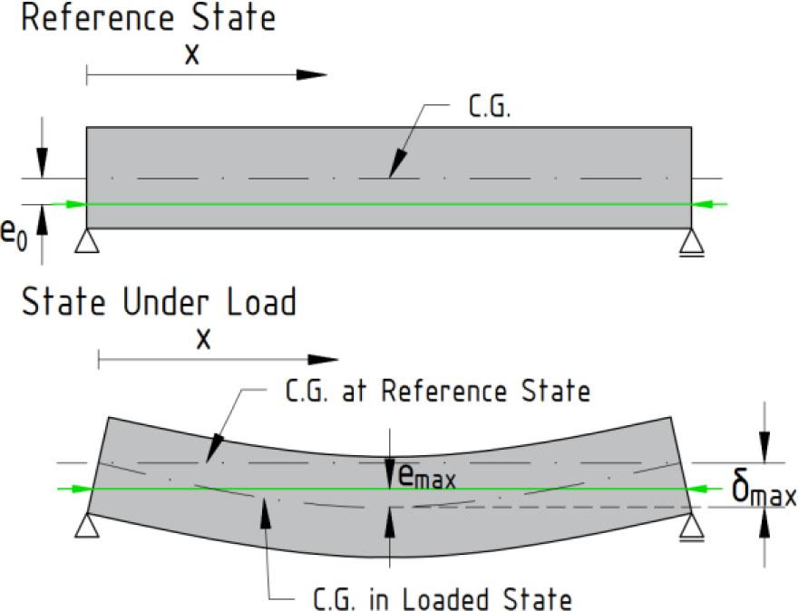
Effect of beam deflection on tendon eccentricity
These secondary effects are typically considered in more advanced nonlinear analyses. In conventional design practice, they are accounted for through safety margins, since linear analysis assumes a fixed tendon geometry. For slender beams, it is advisable to verify whether large deformations could lead to a reduction in prestressing force.
A saddle is an element that changes the direction of the tendon’s profile and transfers radial forces from the tendon into the structure. The curvature radii of saddles are selected as the smallest possible very often, primarily due to spatial constraints. At the interface between the tendon and the saddle, friction develops, which has two main consequences: (1) Losses in prestressing force, as part of the force is consumed in overcoming friction, and (2) Restriction of tendon movement under loading. In the case of an ideally unbonded tendon, the tendon would be free to slip and redistribute stress along its length. However, friction in the saddles inhibits this movement. As loading progresses, the tendon may gradually overcome the frictional resistance, resulting in minor stress redistributions along the tendon, accompanied by slight tendon slips within the saddle. Similarly, under asymmetric or dynamic loading, stress redistribution may occur progressively in the unbonded tendon. Under ideal conditions, a state could be achieved in which the tendon stress becomes uniform along the entire length due to redistribution. However, this tendon movement within the saddle may damage the protective system, and repeated movement can eventually lead to a loss of corrosion protection. The degree of wear on the protective sheathing is strongly influenced by the magnitude of the prestressing force and the surface roughness of the saddle (see Chapter 4).
It follows that the behavior of structures with unbonded tendons is complex and sensitive to various factors, particularly friction in saddles, changes in tendon geometry due to structural deformations, and crack formation. These factors significantly influence both stress distribution and deformation behavior, and therefore require special attention during design, especially with respect to the serviceability limit state. Accurate representation of these effects is only possible through the use of advanced analytical methods, often involving geometric and material nonlinearity.
The use of unbonded tendon, not only in bridge structures, has over the years revealed several characteristics issues that have been documented in technical literature (Tao & Du, 1985; Virlogeux, 1989; Harajli, 1990; Alkhairi, 1991; Harajli, 1993; Brenkus et al., 2017). This section highlights the main problems related to the serviceability limit state.
Before the formation of cracks, structures with unbonded and bonded prestressing tendon behave similarly, and their deflections are comparable. Significant differences only emerge after cracking, as illustrated in Figure 4. Deformations and crack widths increase more rapidly in structures with unbonded tendons due to the lack of bond between the tendons and the surrounding concrete. Since the stress increase in unbonded tendons is smaller, the deflection of the structure grows faster compared to bonded tendons, where the tensile stress is concentrated at the crack locations. This leads to lower stiffness and wider but fewer cracks in unbonded systems. Brenkus et al. (2017) already pointed this out in the early stages of research, and Alkhairi and Naaman (1993) found that, after exceeding the elastic limit, deflection in beams with unbonded tendons increases significantly faster, see Figure 4. For practical design, this means either increasing the amount of prestressing or increasing the amount of non-prestressed reinforcement to prevent excessive cracking and deflections.
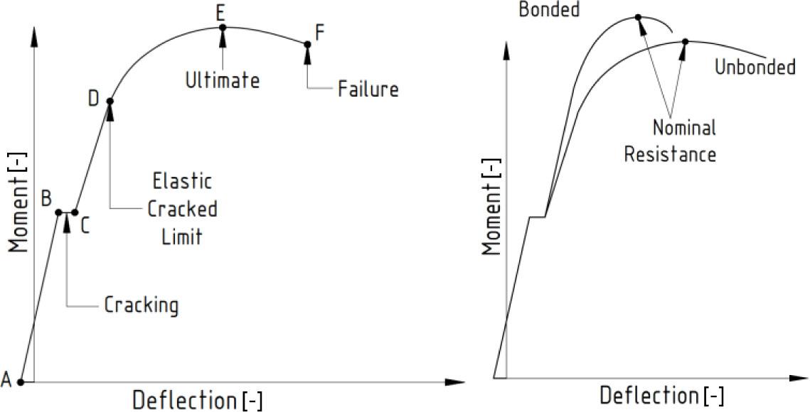
Behavior of different types of prestressing steel during loading (Alkhairi, 1991)
As already mentioned at Figure 1, unbonded prestressing tends to result in fewer cracks, but with greater crack widths. Virlogeux (1983) pointed out that the lack of bond can lead to the formation of a single dominant crack, which may compromise the durability of the structure. Therefore, Alkhairi (1991) recommended combining prestressing steel with an appropriate amount of conventional reinforcement to ensure better crack distribution. Design standards reflect this by requiring a minimum area of conventional (non-prestressed) reinforcement. Codes also limit the allowable crack width, which compels the designer to add either more prestressing steel or conventional reinforcement to prevent cracking.
Due to dynamic, asymmetric, or cyclic loading, minor displacements of the tendon relative to the beam may occur at the saddles, as local static friction is overcome and tendon slip is allowed. If this phenomenon is not considered during design, it may lead to excessive deformation. In the case of external prestressing, friction losses can be significantly lower due to the absence of unpredictable angular changes, since tendons between saddles are straight. Tendon slip depends on the saddle radius, friction between the sheath and saddle, and the type of protective sheath. This slip is accompanied by an increase in tendon stress and minor movements, which can damage the tendon’s protective sheath. Harajli (1990) observed in his experiments that repeated loading leads to degradation of the sheath material at stress concentration zones (specifically, where the tendon contacts the saddle). As will be discussed in one of the following chapters, measurements were conducted to determine the reduction in sheath thickness as a function of saddle radius and prestressing force. In some cases, the material loss reached up to 6% of the original thickness (Klusášek & Svoboda, 2017). These effects can compromise the primary corrosion protection much earlier than in bonded prestressing systems. All these findings highlight the importance of careful detailing of saddle components and rigorous inspection of the entire structure throughout its service life.
To verify the actual behavior of prestressing tendons in saddle with various radii of curvature, a series of short-term experiments was conducted at the Department of Concrete and Masonry Structures at Brno University of Technology (BUT), Faculty of Civil Engineering. These tests focused on the behavior of monostrands (seven-wire strand Y1860-S7-15.7, with an HDPE sheath approximately 2.0 mm thick) in saddles with small radii. The aim of the tests was to examine how radial forces in the saddles affect the monostrand itself, including both the steel cross-section and its protective sheath. For the experiment, a reinforced concrete L-shaped specimen was designed with openings for tendon guidance and an integrated saddle (see Figure 5). The specimen was conceived in such a way that the curvature radius could be changed simply by replacing the saddle. The saddle itself was made of steel strip bent to the required radius. To measure the relevant parameters, several instruments were used: inductive sensors to monitor displacements, strand flattening, and elongation; magnetoelastic sensors to measure mechanical stress in the tested strands; and feeler gauges to assess the thinning of the HDPE sheath (Svoboda et al., 2016).
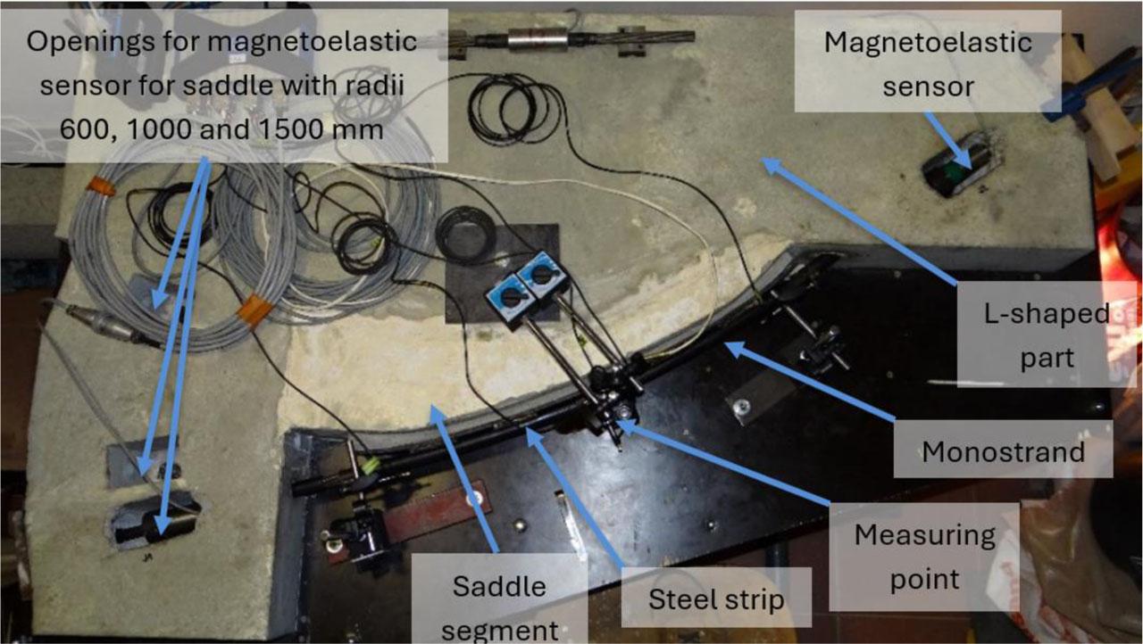
Test specimen (Svoboda & Klusáček, 2018)
The test specimen consists of two concrete parts (L-shaped part and saddle segment) to enable measurements at different radii of curvature of the prestressing tendons. The first part of specimen is a reinforced concrete L-shaped segment with dimension 1375×900 mm and a constant thickness of 120 mm. This part serves as the base for the saddle segment. The second part is an additionally cast saddle segment with a thickness of 120 mm, which fills the inner space of the main base part and, with its curved shape, allows the installation of the saddle. The saddle part permits changes in the radius of curvature by removing and recasting a new segment of the required shape. The test specimen was designed for measuring monostrands at curvature radii of 600, 1000 and 1500 mm. The saddle of the test specimen is made of flat structural steel strips and is in the UHPC saddle part of the test specimen. The strip steel has length of 700 mm, a width of 50 mm and thickness of 5 mm. Monostrands are guided on the saddle by welded steel bars with a diameter of 8 mm and length of 50 mm, at regular intervals of 100 mm (Svoboda et al., 2016).
For measuring prestressing force was used magnetoelastic sensor, which are placed in openings in L-shaped segment of test specimen. This measuring method is based on utilization of changes in the physical properties of ferromagnetic materials under load. In the half of curvature of test specimen was point where flattening (loss of cross-sectional circularity) of monostrands and thinning of HDPE sheath was measured. In his point was sheath from strand removed and an inductive sensor with a spring-loaded tip with a range of 5 mm was installed (see Figure 6). With this sensor it was able to measure displacement, flattening and elongation of monostrand. Together with flattening was thinning of HDPE sheath measured. On the strand where was sheath removed it was possible to measure the thinning of sheath with steel leaf gauge with an accuracy of one hundredth of a millimeter (Svoboda et al., 2016).
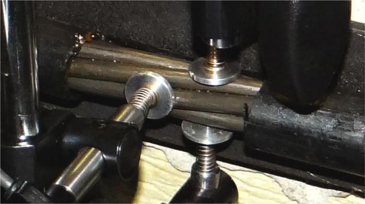
Three inductive sensors for measuring strand displacement and flattening (Svoboda & Klusáček, 2018)
So far, measurements have been carried out on saddle with a curvature radius of 1.50 m and on two series of prestressing tendons from different suppliers, result of tendon from first supplier are shown in red in figures and labeled with numbers 01, 02 and 04 and from second supplier are shown in blue and labeled with numbers 1701, 1702 and 1703, there are no main difference between that type of tendon. The loading step by prestressing force was chosen value of 20 kN up to maximum force 200 kN, for typical process see Figure 7 (Svoboda et al., 2016).
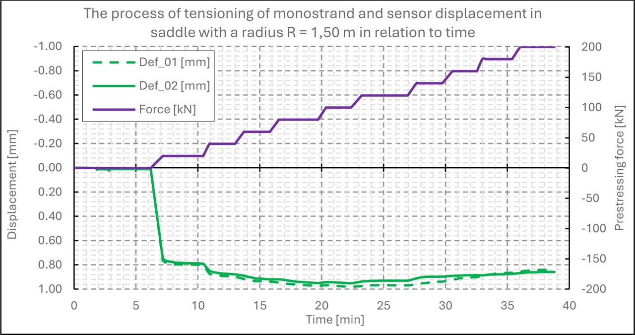
Typical tensioning of monostrand and sensor displacement under load (Svoboda & Klusáček, 2018)
The flattening of strand (loss of cross-sectional circularity) can be numerically derived from the data measured by the three inductive displacement sensors. The sensors measured the displacement of the strand in two mutually perpendicular planes (see Figure 8). The sensors labeled Def_1 and Def_2 measured the displacement of the prestressing tendon against each other in a plane parallel to the plane of the saddle contact surface. The Def_3 sensor measured the displacement of the monostrand in a plane perpendicular to the plane of the saddle contact surface. From the known displacement values, it is possible to quantify the resulting flattening of the monostrand as:
Δd|| - flattening of the strand in the plane parallel to the plane of the saddle contact surface,
dDef_1 - displacement value of Def_1 sensor
dDef_2 - displacement value of Def_2 sensor.
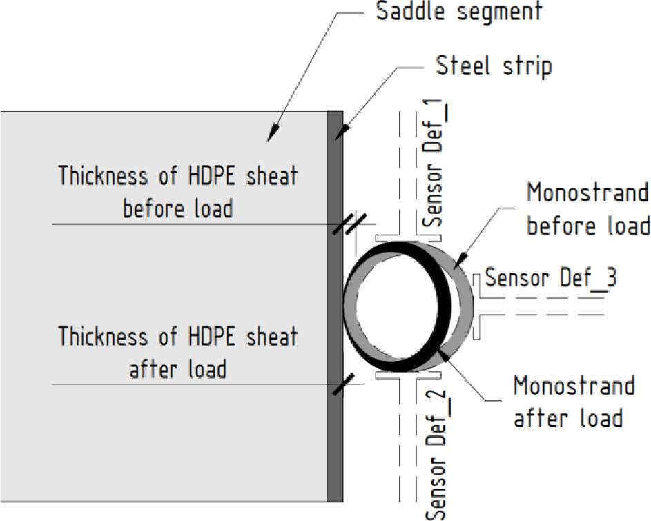
Scheme of measuring flattening and HDPE sheath thinning (Svoboda et al., 2016)
The evaluation was performed by substituting values at corresponding times and searching for the maximum flattening values (Svoboda et al., 2016).
At smaller saddle curvature radii, the strand cross-section may become flattened, potentially compromising the integrity of the HDPE sheath. The measured values indicate the extent of flattening under corresponding prestressing force. The maximum observed flattening was around 1–2%, see Figure 9. In addition to cross-sectional deformation, the deformation of the HDPE sheath was also examined. Due to the radial forces generated by prestressing, which are directly related to the curvature radius of the saddle, the HDPE sheath, which serves as the primary corrosion protection for the strand, becomes thinned. At a maximum force of 200 kN, the thinning was measured to be in the range of 0.123–0.253 mm, which corresponds to approximately 6% of the original sheath thickness, see Figure 10. These measurements highlight the stringent requirements for the quality of the saddle contact surfaces. Even the slightest inaccuracy or unevenness can lead to the degradation of the primary protective function of the prestressing system.
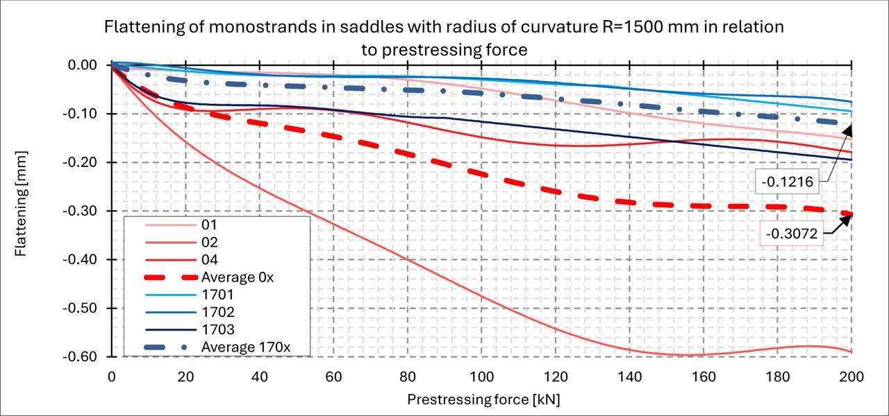
Result of experimental measurements of flattening of monostrands in saddles with radius of curvature 1500 mm (Svoboda & Klusáček, 2018)
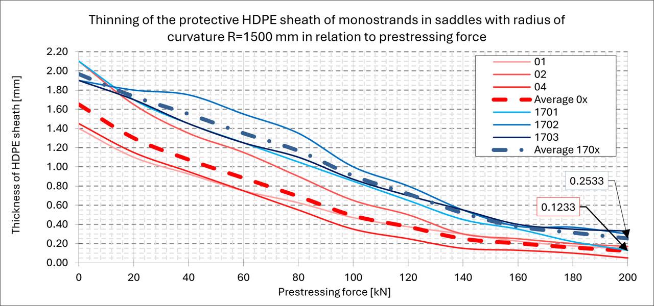
Result of experimental measurements of thinning of the protective HDPE sheath of monostrands in saddles with radius of curvature 1500 mm (Svoboda & Klusáček, 2018)
The use of unbonded prestressing tendons in bridge structures offers significant advantages in terms of increased load-carrying capacity and the ability to strengthen existing structures. However, it places high demands on design with respect to serviceability limit states. Design approaches must ensure the prevention of crack propagation and the preservation of the corrosion protection of the unbonded tendons. Based on the preceding discussion, the following recommendations for engineering practice can be drawn:
- ○
Saddle design – The radius of curvature should be as large as possible in order to minimize friction and radial pressure on the tendon (and its protective sheathing). Potential wear of the HDPE sheath due to cyclic or dynamic loading, which may cause tendon slip within the saddle, must be considered. - ○
Durability assurance – The primary protection of the tendon must remain intact for the entire service life. Design should avoid excessive radial forces in saddles by properly aligning tendon profiles, and constriction must ensure that saddle surfaces are manufactured to a high quality to prevent sheath cutting or significant thinning. - ○
Control of cracking and deflections – In addition to unbonded prestressing, a suitable amount of non-prestressed reinforcement should be provided in the tension zones of cross-sections to limit crack initiation and propagation.
Previous research has revealed several gaps in knowledge and understanding, such as long-term effects in combination with unbonded prestressing (e.g. the influence of time-dependent behavior of concrete, asymmetric or cyclic loading), or the impact of dynamic loading on the redistribution of stress in the prestressing tendons. These areas represent promising directions for future research.
In conclusion, unbonded prestressing represents an effective tool for increasing the load-bearing capacity and extending the service life of bridge structures, but only if it is designed and implemented with a full understanding of its specific structural behavior. Ensuring compliance with serviceability limit states is essential, and engineers are encouraged to apply modern research findings and recommended design practices. When properly designed, unbonded prestressing steel can provide bridges with a safe and long-term benefit in the form of high-capacity reserves and extended durability.