
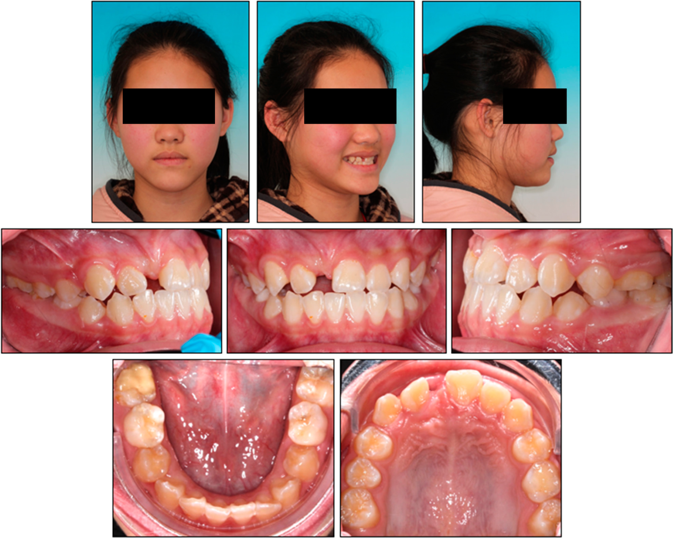
Figure 1.
Pre-treatment extraoral and intraoral photographs.
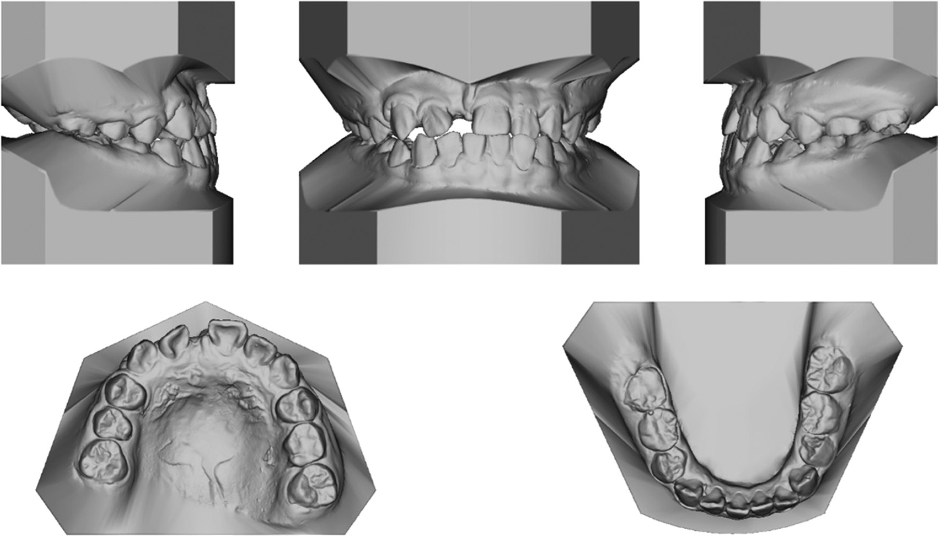
Figure 2.
Pre-treatment dental casts.
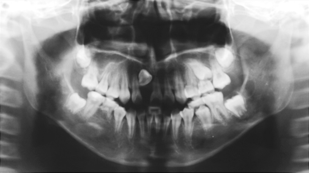
Figure 3.
Pre-treatment panoramic radiograph.
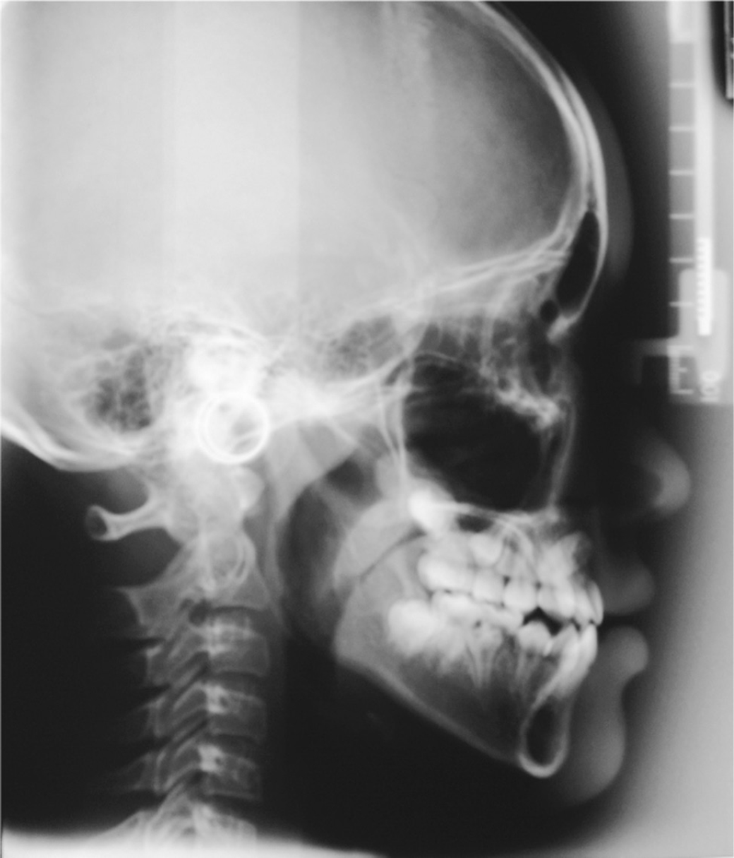
Figure 4.
Pre-treatment lateral cephalogram.
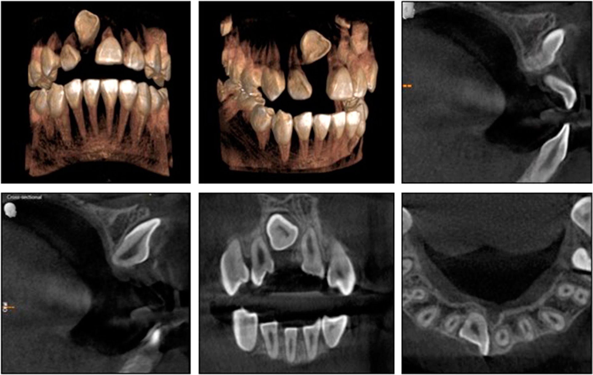
Figure 5.
Pre-treatment cone-beam computed tomography (CBCT).
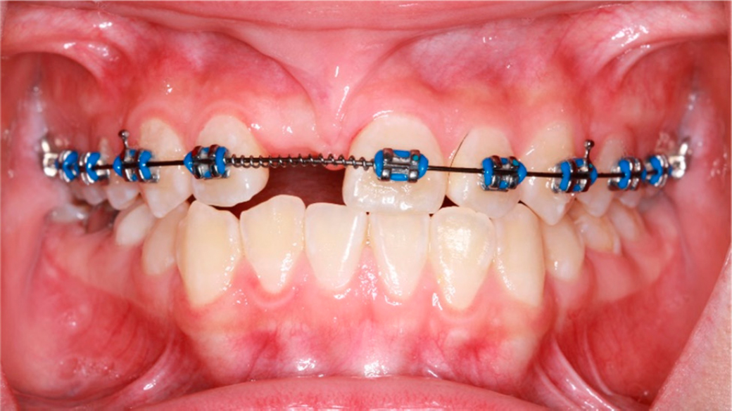
Figure 6.
Pre-surgical intraoral photo.
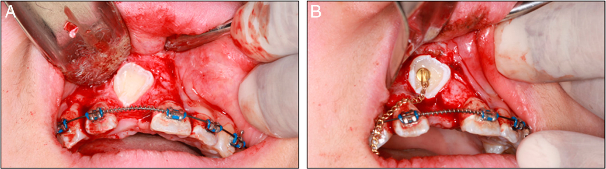
Figure 7.
(A) Surgical exposure of the impacted 11; (B) Placement of the button with gold chain on the 11.

Figure 8.
(A) The Ballista spring to encourage more vertical movement; (B) Power chain to encourage palatal crown movement; (C) 11 achieved final alignment.
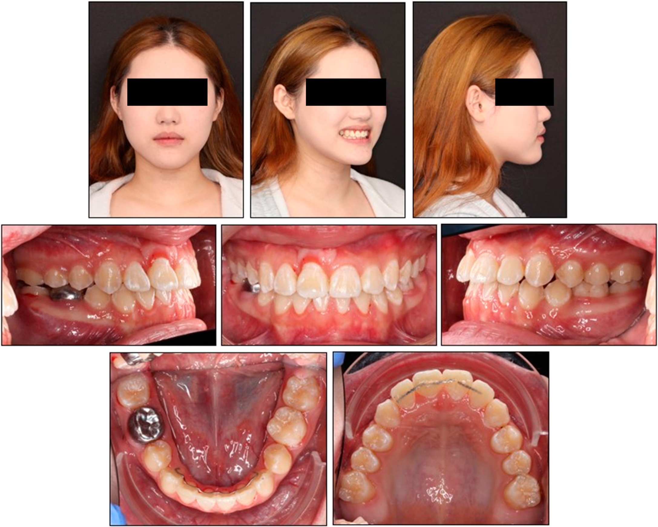
Figure 9.
Debond extraoral and intraoral photographs.
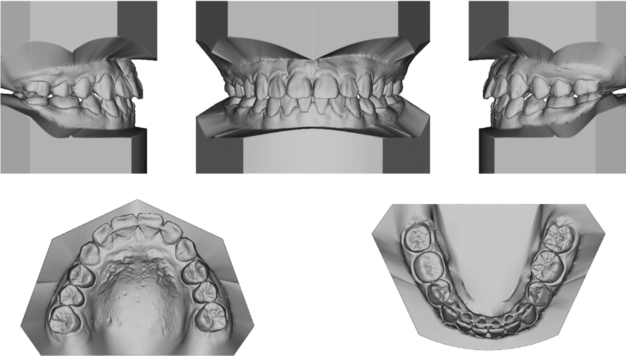
Figure 10.
Debond casts.
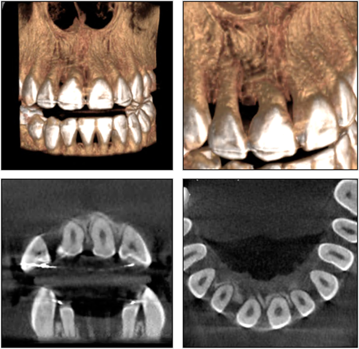
Figure 11.
Post-op cone-beam computed tomography (CBCT).
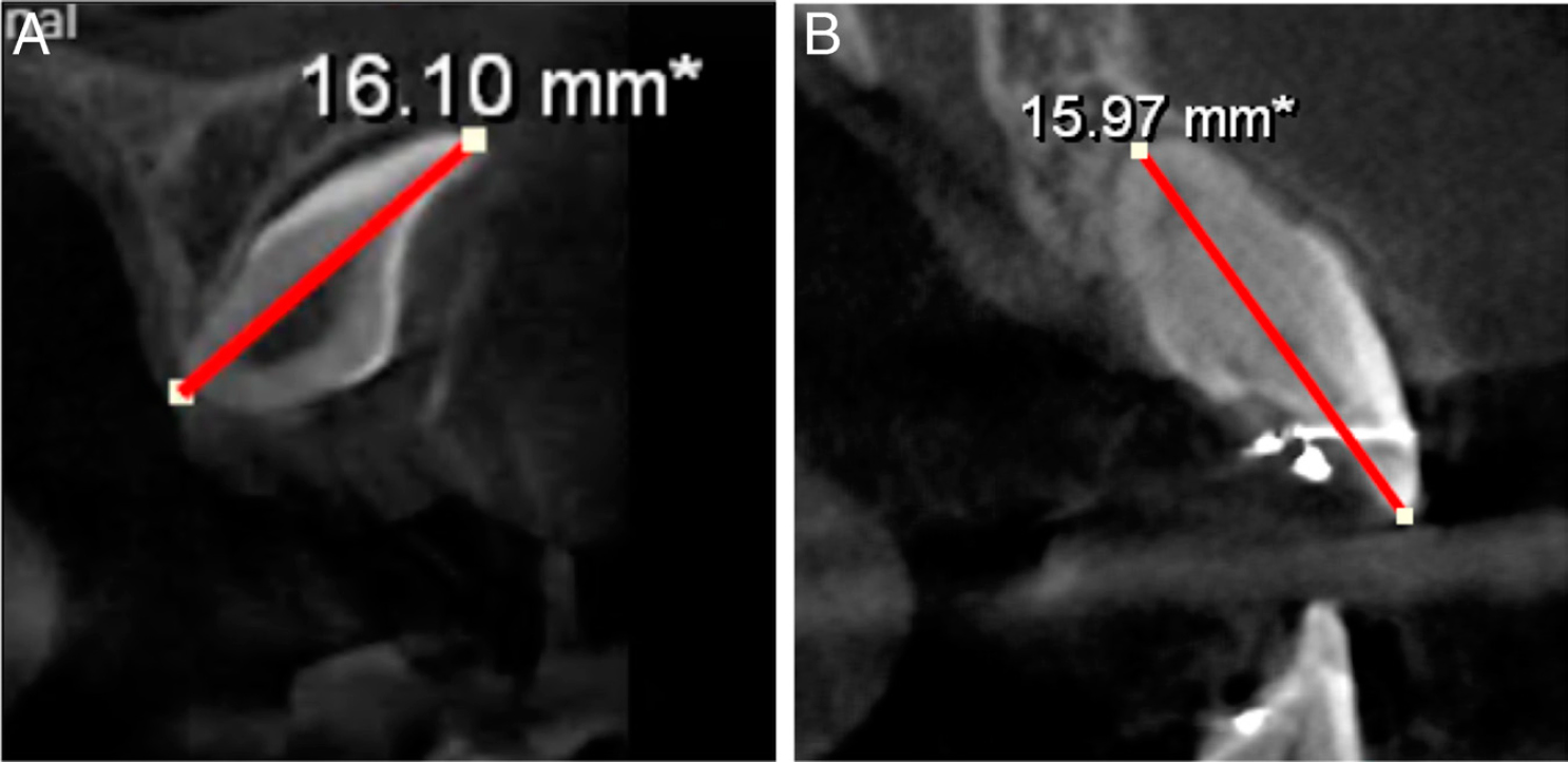
Figure 12.
Root length of the dilacerated impacted tooth 11 on the cone-beam computed tomography (CBCT). (A) Pre-op root length was 16.10mm; (B) Post-op 11 root length was 15.97 mm.
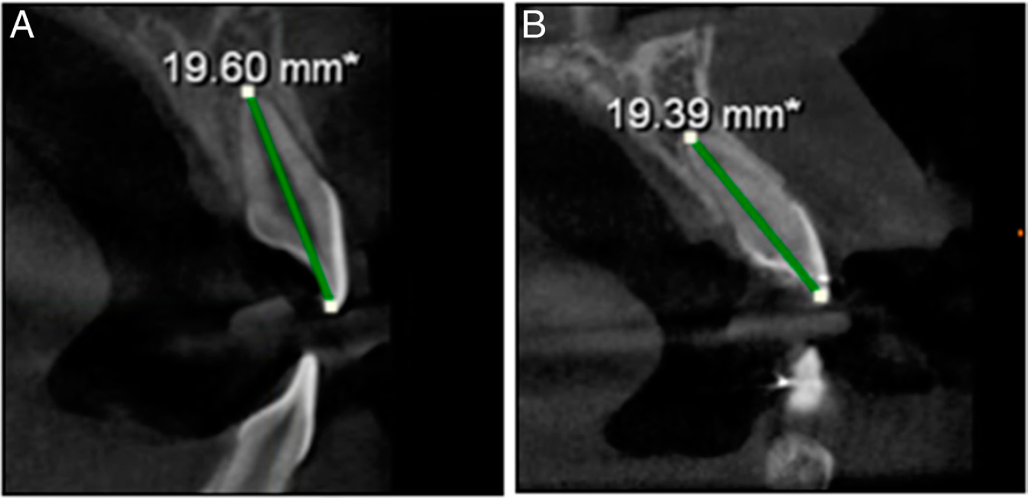
Figure 13.
Root length of the control tooth 21 on the cone-beam computed tomography (CBCT). (A) Pre-op root length was 19.60 mm; (B) Post-op 21 root length was 19.39 mm.