
1. Introduction
For many years, transparent building envelopes (windows, glass facades) were considered an element generating large heat losses. The concept of insulating glass units (IGUs) has allowed for a significant reduction in these losses. The combination of glass panes creating a tight cavity filled with gas [1,2] allowed the use of glass with thin low-emission films, thanks to which the insulation of the glazing was significantly improved [3,4]. However, the use of this construction had a certain side effect, regarding the static operation of the set of glass panes. It was already noted in the 1970s that the tightness of the inter-pane cavity generates loads not encountered in other building elements [5]. In the sealed cavities, certain initial conditions of pressure, temperature, and gas volume are enclosed, resulting from the conditions prevailing during the production of IGUs. In operating conditions, any temporary or periodic change in atmospheric pressure or temperature is a load that causes deflection and stress of the component panes – they take on a concave deflection form or “bulge” (Figure 1). It was also noticed that the change in gas volume resulting from the deflection of glass panes generates a pressure change in the cavities [6,7]. This change (gas interaction) partially compensates for external influences. Static quantities (deflection, stress) in the IGUs therefore result from the state of temporary equilibrium between the gas parameters in the cavities and the current weather conditions [8].
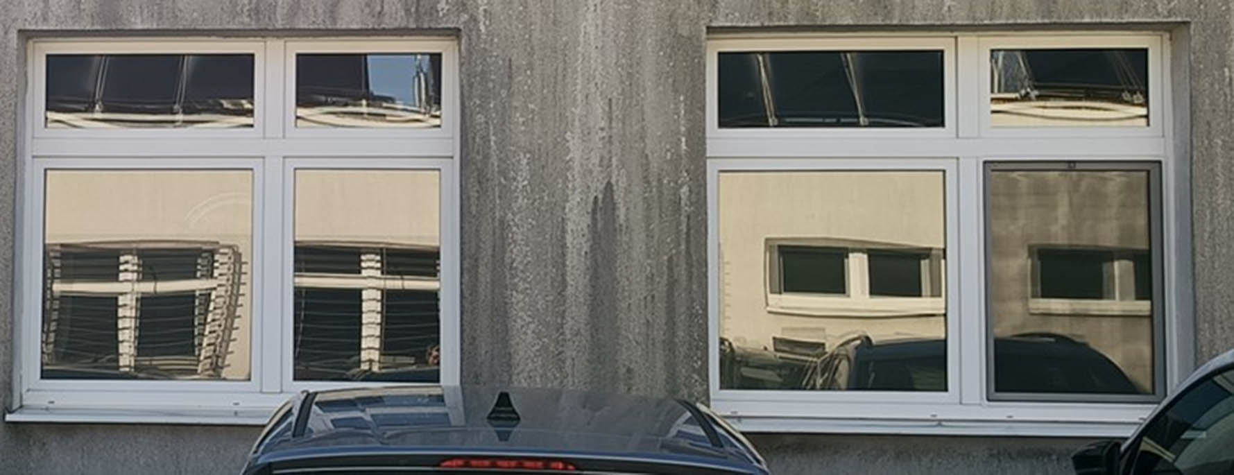
Figure 1
“Pillowing” of IGU component panes causing distortion of the reflected image.
Source: Author’s contribution.
Theoretical models of static behavior of IGUs are well known. The often cited publications of Feldmeier [6,7] are considered classic, as he noticed that increasing the IGU’s linear dimensions (width, length) significantly increases the gas interaction in the cavities – high susceptibility to deflection of the component panes causes large changes in the cavity volume. For this reason, for each IGU, there is a characteristic (critical) width, at which the stresses in the glass are the highest. The literature also describes other analytical and numerical models, mostly based on Kirchhoff–Love plate theory and ideal gas law [9,10,11,12,13], as well as using Betti’s analytical method and Green’s functions [14,15]. Experimental research in this area is quite difficult; however, it can be noted that in recent years several instrumental studies have been carried out [16,17,18,19], also in the field of determining the performance of gas coupling (load sharing) between the component panes [20,21,22]. Experimental and numerical tests of the edge connection efficiency in IGUs were also performed [23,24].
For many years, double-glazed IGUs were mainly used in construction, but the regulations and guidelines regarding the thermal protection of buildings were gradually tightened. For example, in Poland, since 2021, the maximum thermal transmittance for external glazing is 0.9 W/(m2 K) [25]. This level of requirements necessitates the use of triple- and multi-glazed IGUs in residential buildings. Calculation practice has shown that increasing the total thickness of the recesses causes almost proportionally higher static values in IGUs [26]. Thick inter-pane spaces are also used in closed cavity facade systems [27]. A significant increase in the effects of climatic loads also occurs in IGUs with curved glass [28]. Therefore, for some time now, solutions have been proposed to reduce climatic loads by equalizing the pressure between the recesses and the atmospheric air.
The classic solution in this area are capillaries or bi-directional valves installed inside the edge spacer. There are continuous or one-time pressure equalization systems. The latter method is recommended when the climatic conditions at the place of use are significantly different from the conditions at the time of production – for example, in mountainous regions, the barometric air pressure is much lower than in the lowlands [29,30]. These systems have certain drawbacks related to the possibility of reducing the thermal insulation performance of the glazing. First, filling the cavities with argon becomes questionable – this gas is replaced with air, which insulates worse. Second, water vapor can get into the gap and destroy the sensitive low-emission film, which is a barrier to heat loss. The latter problem is proposed to be solved by using a membrane impermeable to water vapor in the pressure equalization device [31]. The above solutions are available on the market, but considering the described limitations, they are not used on a large scale.
A certain intermediate solution is also possible – maintaining the tightness of the outer panes (no possibility of gas exchange between the IGU and atmospheric air), but equalizing the internal pressure between the cavities in the multi-glazed unit. Such a solution was proposed by Kralj et al. [32], describing six-glazed IGUs. Internal pressure equalization is realized here by making 3 mm holes in the internal IGU panes. The possibility of equalizing the internal pressure in triple-glazed IGUs was also analyzed by Respondek [33]. It was noted that pressure equalization can be beneficial in the context of minimizing the load on the internal pane of triple-glazed IGU – thinner glass can be used here without the risk of excessive stress.
The aim of this article is to analyze the effect of internal pressure equalization, in selected configurations of the IGU structure and load, on the static quantities in the outer component glass panes. Triple- and quadruple-glazing IGUs subjected to uneven loads of temperature drops in the cavities in winter conditions were analyzed. Horizontal and vertical location of the IGUs and the possibility of radiative cooling of glazing surface, under certain operating conditions were also considered.
2. Methodology of research
The analytical model described in previous literature [11,34] was used to determine the static quantities in climatically loaded IGUs. This model was experimentally validated [18,28].
The basis for estimating the deflection and stress values in IGUs is the calculation of the internal gas pressure in each cavity of a climatically loaded IGU. Under the influence of these loads, the IGU component panes deflect, which results in the volume change of gas cavities and gas pressure. For each cavity, an equation can be formulated describing the state of temporary equilibrium between external influences and the internal pressure. It is assumed that the gas obeys the ideal gas law, and the volume change is calculated based on the integrated deflection function. Finally, an equation (double-glazed IGUs) or a system of quadratic equations (multi-glazed IGUs) is obtained, the solution of which is the operating gas pressure in the cavities. Then, based on the pressure difference between the cavities (or between a cavity and the surroundings, taking into account external loads), the uniformly distributed resultant load q (kN/m2) is estimated for each IGU component pane. Knowledge of the resultant load allows the calculation of extreme static quantities for each of the component panes based on equations known from plate theory.
The model allows for the analysis of flat IGUs with any number of cavities for various geometric parameters, it is also possible to take into account the self-weight of the glass panes (horizontally and diagonally located IGUs). For internally unsealed multi-glazed IGUs, calculations were performed as for double-glazed ones with a cavity of total thickness.
The disadvantage of the model is that its application is limited to the range of linear-elastic deflection of the component panes (small deflections). According to Klindt et al. [35], this assumption is sufficiently accurate, if the deflection is smaller than the pane thickness. For this reason, the climatic load assumed in the analyzed examples was selected so that this condition was met.
For the example IGUs, the following were calculated: resultant load q for each IGU component glass pane, maximum deflection of component panes w (mm) and maximum stress σ x (MPa). The resultant load q describes the pressure difference (over- or underpressure) between a cavity and atmospheric air (outer panes “ex” and “in”) or between the cavities (internal panes 1–2 and 2–3). Figure 2 shows the subscripts used to designate the individual component panes and cavities. The resultant load q and deflection w facing the interior were considered positive, with respect to the stress, the results present absolute values.
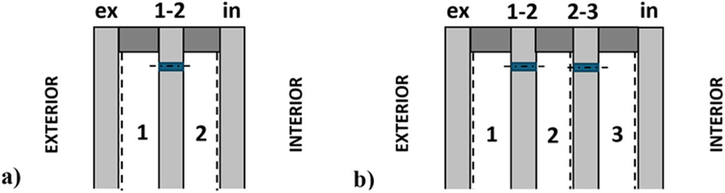
Figure 2
Subscripts used to designate component panes and cavities; location of low-e films (dashed line): (a) 3-glazed IGU and (b) 4-glazed IGU.
Source: Author’s contribution.
Triple- and quadruple-glazed IGUs with dimensions of 60 × 120 cm2 were analyzed in three construction variants:
symmetrical structure (SYM IGU) – all component panes are 4 mm thick, and all argon-filled cavities are 12 mm thick,
asymmetrical structure (LAM IGU) – as above, except that the outer pane “in” was replaced with laminated glass pane 44.2 (two 4 mm glass sheets connected with double foil interlayer); this is a frequently used system in horizontal and diagonal glazing,
additionally, for comparison, a “reversed” structure (RLAM IGU) was analyzed, where laminated glass was used as pane “ex.”
The calculations assumed the equivalent thickness of laminated glass pane according to the standard [36]: 6.63 mm for deflection and 7.32 mm for stress. The glass parameters were assumed according to the standard [37]: Young’s modulus 70 GPa and Poisson’s ratio 0.2. The initial gas parameters were also assumed (with these parameters, deflections and stresses in an IGU are 0): an initial pressure of 100 kPa and an initial temperature of 20°C (293.15 K).
Analyses presented in previous works [38] show that for multi-glazed IGUs, asymmetrical loads can be particularly dangerous, in particular, temperature differences in individual cavities of the multi-glazed IGUs. Such a case occurs in winter operating conditions, which was assumed as the climatic load of the IGUs. Room temperature t i = 20°C and external air temperature t e = −10°C were assumed. To determine the temperature load, based on the theoretical temperature distribution in an IGU (steady state of heat flow), the average gas temperature t m (°C) was determined for each cavity. The thermal resistance of the cavities was calculated using the standard [39], assuming that each cavity is adjacent to one surface with a low-emission film with emissivity ε = 0.04 (Figure 2).
For horizontal location, the possibility of additional temperature differentiation in the cavities under radiative cooling conditions was also considered. This phenomenon is manifested by a temperature drop on horizontal and oblique surfaces (ground, roofs) even below the air temperature [40,41,42,43]. Radiative cooling is observed in cloudless sky conditions, at night. It is caused by the so-called “atmospheric window.” In the electromagnetic wave range of 8–13 μm, the Earth’s atmosphere is transparent. In the absence of cloud cover, this radiation is easily transmitted into space. In principle, the phenomenon does not concern vertical envelopes – rather they exchange heat by radiation with the neighboring buildings, landscape surroundings, etc. Radiative cooling is also called “cold sky effect.” In the calculations, the radiation temperature of the atmosphere t r (°C) was assumed according to the formula given by Nowak [42] for average conditions in Poland:
In the analyzed case t r = −32.34°C. The temperature distribution under radiative cooling conditions was calculated assuming that the external surface of the horizontal IGU exchanges heat by convection with the atmospheric air (t e), and by radiation with the “cold sky” (t r). The applied calculation methodology is described in the study by Respondek [44].3. Results
3.1. Temperature distribution in IGUs
Tables 1 and 2 present the results of temperature distribution calculations for several cases of double-, triple-, and quadruple IGUs under different operating conditions. The horizontal and vertical locations were analyzed. For the horizontal location, standard conditions (cloudy sky) and radiative cooling conditions were considered. The results determined at wind speed of 4 m/s (standard conditions [39]) and in windless conditions were also compared. The average gas temperature t m (°C) in each of the cavities was calculated. Additionally, for illustrative purposes, the temperature on both outer surfaces of IGUs ϑ ex, ϑ in (°C) and thermal transmittance U (W/m2K), calculated according to the standard [39], are shown (in radiative cooling conditions, the equivalent U-value resulting from the heat flux density was calculated). Example temperature distributions are illustrated in Figure 3.
Table 1
Temperature distribution in IGUs at wind speed of 4 m/s
| Parameter | Vertical IGU, t e = −10°C | Horizontal IGU, cloudy sky, t e = −10°C | Horizontal IGU, clear sky, t e = −10°C, t r = −32.34°C | ||||||
|---|---|---|---|---|---|---|---|---|---|
| 2-glazed | 3-glazed | 4-glazed | 2-glazed | 3-glazed | 4-glazed | 2-glazed | 3-glazed | 4-glazed | |
| ϑ ex (°C) | −8.44 | −9.12 | −9.40 | −7.56 | −8.73 | −9.18 | −10.17 | −11.47 | −11.97 |
| t m1 (°C) | 3.39 | −2.30 | −4.61 | 3.35 | −2.29 | −4.63 | 1.71 | −4.44 | −7.00 |
| t m2 (°C) | − | 10.88 | 4.73 | − | 10.52 | 4.40 | − | 9.56 | 2.88 |
| t m3 (°C) | − | − | 13.72 | − | − | 13.48 | − | − | 12.81 |
| ϑ in (°C) | 15.22 | 17.34 | 18.16 | 14.26 | 17.01 | 18.06 | 13.61 | 16.66 | 17.83 |
| U (W/m2K) | 1.225 | 0.683 | 0.472 | 1.914 | 0.997 | 0.645 | 2.132 | 1.113 | 0.722 |
Source: Author’s contribution.
Table 2
Temperature distribution in IGUs, in windless weather
| Parameter | Vertical IGU, t e = −10°C | Horizontal IGU, cloudy sky, t e = −10°C | Horizontal IGU, clear sky, t e = −10°C, t r = −32.34°C | ||||||
|---|---|---|---|---|---|---|---|---|---|
| 2-glazed | 3-glazed | 4-glazed | 2-glazed | 3-glazed | 4-glazed | 2-glazed | 3-glazed | 4-glazed | |
| ϑ ex (°C) | −5.60 | −7.43 | −8.19 | −3.68 | −6.42 | −7.59 | −10.43 | −14.20 | −15.85 |
| t m1 (°C) | 5.04 | −1.01 | −3.60 | 5.76 | −0.49 | −3.29 | 1.55 | −6.57 | −10.92 |
| t m2 (°C) | − | 11.42 | 5.36 | − | 11.23 | 5.26 | − | 8.60 | 0.77 |
| t m3 (°C) | − | − | 13.98 | − | − | 13.85 | − | − | 11.88 |
| ϑ in (°C) | 15.69 | 17.49 | 18.23 | 15.21 | 17.30 | 18.19 | 13.54 | 16.30 | 17.50 |
| U (W/m2K) | 1.105 | 0.644 | 0.453 | 1.597 | 0.899 | 0.603 | 2.154 | 1.232 | 0.832 |
Source: Author’s contribution.
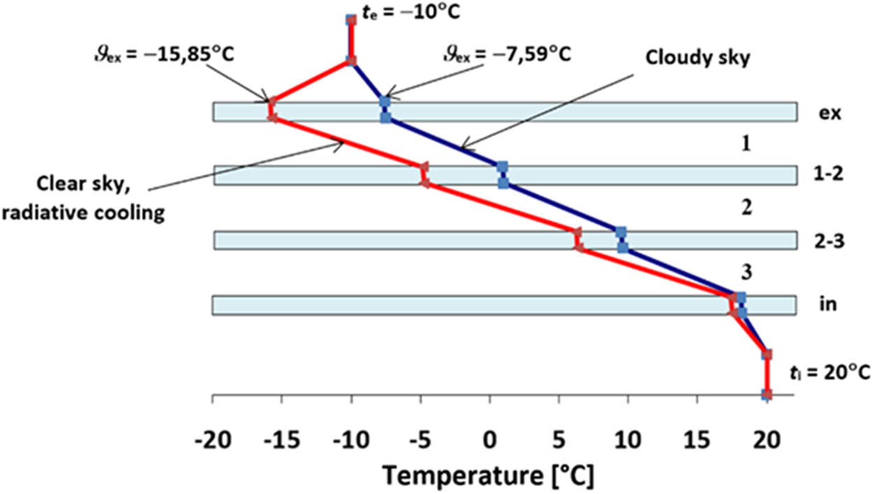
Figure 3
Temperature distribution in a quadruple-glazed IGU located horizontally (no wind).
Source: Author’s contribution.
The calculations show that for vertical location, the temperature differences in the cavities are greater for standard conditions (wind speed 4 m/s) than in the absence of wind. However, in the case of horizontal location, under radiative cooling conditions, the temperature on the external surfaces of IGUs drops below the external air temperature, which results in temperature decrease in the cavities. The phenomenon of radiative cooling increases in windless weather. As a result, the data marked in bold values in Tables 1 and 2 were selected for the calculations of static quantities (Section 3.2).
3.2. Static quantities in example IGUs
Static quantities for each of the IGU component panes, with the parameters described in Section 2, were calculated for two variants: sealed cavities and internally unsealed cavities. The IGUs were loaded with different temperature drops, as described in Section 3.1. For the horizontal position, an additional self-weight of 25 kN/m3 was taken into account, according to the standard [37]. The calculation results are presented in Table 3 (for SYM IGUs) and Table 5 (for LAM IGUs). The extreme deflection and stress for each analyzed IGU are marked in bold values. These extreme values occur in the glass pane “ex” (except for vertically located, internally unsealed IGUs, when the loads on both outer panes are equal).
Table 3
Static quantities in SYM IGUs (4-12-4-12-4 or 4-12-4-12-4-12-4)
| IGU type, location | Glass pane | Sealed cavities | Internally unsealed cavities | ||||
|---|---|---|---|---|---|---|---|
| q (kN/m2) | w (mm) | σ x (MPa) | q (kN/m2) | w (mm) | σ x (MPa) | ||
| 3-glazed IGU, vertically | ex | 0.467 | 1.58 | 6.30 | 0.407 | 1.37 | 5.49 |
| 1-2 | −0.120 | −0.40 | 1.62 | — | — | — | |
| in | −0.347 | −1.17 | 4.68 | −0.407 | −1.37 | 5.49 | |
| 4-glazed IGU, vertically | ex | 0.694 | 2.34 | 9.37 | 0.576 | 1.95 | 7.78 |
| 1-2 | 0.060 | 0.20 | 0.81 | — | — | — | |
| 2-3 | −0.307 | −1.04 | 4.15 | — | — | — | |
| in | −0.447 | −1.51 | 6.03 | −0.576 | −1.95 | 7.78 | |
| 3-glazed IGU, horizontally | ex | 0.661 | 2.23 | 8.93 | 0.592 | 2.00 | 7.99 |
| 1-2 | −0.038 | −0.13 | 0.51 | 0.100 | 0.34 | 1.35 | |
| in | −0.323 | −1.09 | 4.36 | −0.392 | −1.32 | 5.29 | |
| 4-glazed IGU, horizontally | ex | 0.975 | 3.29 | 13.17 | 0.828 | 2.80 | 11.18 |
| 1-2 | 0.178 | 0.60 | 2.40 | 0.100 | 0.34 | 1.35 | |
| 2-3 | −0.286 | −0.96 | 3.86 | 0.100 | 0.34 | 1.35 | |
| in | −0.467 | −1.58 | 6.31 | −0.628 | −2.12 | 8.48 | |
Source: Author’s contribution.
The critical widths a cr (cm) for each analyzed case (with the aspect ratio constant at 2.0) and the static quantities for the IGUs for these dimensions were also calculated (Tables 4 and 6). Additionally, the static quantities in the “reversed” pane arrangement (RLAM IGU) were determined – the results for the critical widths are presented in Table 7. In Tables 4, 6, and 7, the Diff-value indicates the percentage effect of the internal pressure equalization on the extreme static quantities in IGUs.
Table 4
Static quantities in SYM IGUs for critical widths
| IGU type, location | Sealed cavities | Internally unsealed cavities | Diff | ||||||
|---|---|---|---|---|---|---|---|---|---|
| a cr (cm) | q (kPa) | w (mm) | σ x (MPa) | a cr (cm) | q (kPa) | w (mm) | σ x (MPa) | ||
| 3-glazed IGU, vertically | 30.8 | 3.602 | 0.84 | 12.82 | 32.1 | 2.716 | 0.75 | 10.49 | −18,2% |
| 4-glazed IGU, vertically | 33.9 | 3.702 | 1.27 | 15.96 | 35.5 | 2.660 | 1.10 | 12.58 | −21,2% |
| 3-glazed IGU, horizontally | 31.1 | 4.344 | 1.06 | 15.76 | 32.6 | 3.292 | 0.97 | 13.10 | −16,9% |
| 4-glazed IGU, horizontally | 33.7 | 4.838 | 1.63 | 20.60 | 36.0 | 3.369 | 1.48 | 16.41 | −20,4% |
Source: Author’s contribution.
Table 5
Static quantities LAM IGUs (4-12-4-12-44.2 or 4-12-4-12-4-12-44.2)
| IGU type, location | Glass pane | Sealed cavities | Internally unsealed cavities | ||||
|---|---|---|---|---|---|---|---|
| q (kN/m2) | w (mm) | σ x (MPa) | q (kN/m2) | w (mm) | σ x (MPa) | ||
| 3-glazed IGU, vertically | ex | 0.626 | 2.11 | 8.46 | 0.637 | 2.15 | 8.60 |
| 1-2 | 0.052 | 0.17 | 0.70 | — | — | — | |
| in | −0.678 | −0.50 | 2.73 | −0.637 | −0.47 | 2.57 | |
| 4-glazed IGU, vertically | ex | 0.850 | 2.87 | 11.48 | 0.886 | 2.99 | 11.96 |
| 1-2 | 0.228 | 0.77 | 3.08 | — | — | — | |
| 2-3 | −0.114 | −0.38 | 1.54 | — | — | — | |
| in | −0.964 | −0.71 | 3.89 | −0.886 | −0.66 | 3.57 | |
| 3-glazed IGU, horizontally | ex | 0.823 | 2.78 | 11.11 | 0.830 | 2.80 | 11.20 |
| 1-2 | 0.136 | 0.46 | 1.83 | 0.100 | 0.34 | 1.35 | |
| in | −0.558 | −0.41 | 2.25 | −0.530 | −0.39 | 2.14 | |
| 4-glazed IGU, horizontally | ex | 1.149 | 3.88 | 15.51 | 1.181 | 3.99 | 15.95 |
| 1-2 | 0.364 | 1.23 | 4.91 | 0.100 | 0.34 | 1.35 | |
| 2-3 | −0.071 | −0.24 | 0.96 | 0.100 | 0.34 | 1.35 | |
| in | -0.942 | -0.70 | −3.80 | −0.881 | −0.65 | 3.55 | |
Source: Author’s contribution.
Table 6
Static quantities in LAM IGUs for critical widths
| IGU type, location | Sealed cavities | Internally unsealed cavities | Diff | ||||||
|---|---|---|---|---|---|---|---|---|---|
| a cr (cm) | q (kPa) | w (mm) | σ x (MPa) | a cr (cm) | q (kPa) | w (mm) | σ x (MPa) | ||
| 3-glazed IGU, vertically | 34.1 | 3.203 | 1.13 | 13.97 | 36.3 | 2.716 | 1.23 | 13.43 | −3,9% |
| 4-glazed IGU, vertically | 36.1 | 3.388 | 1.5 | 16.56 | 40.2 | 2.660 | 1.81 | 16.11 | −2,7% |
| 3-glazed IGU, horizontally | 33.9 | 3.994 | 1.37 | 17.21 | 36.6 | 3.316 | 1.55 | 16.65 | −3,3% |
| 4-glazed IGU, horizontally | 36.5 | 4.289 | 1.98 | 21.43 | 40.1 | 3.394 | 2.38 | 20.87 | −2,6% |
Source: Author’s contribution.
Table 7
Static quantities in RLAM IGUs for critical widths
| IGU type, location | Sealed cavities | Internally unsealed cavities | Diff | ||||||
|---|---|---|---|---|---|---|---|---|---|
| a cr (cm) | q (kPa) | w (mm) | σ x (MPa) | a cr (cm) | q (kPa) | w (mm) | σ x (MPa) | ||
| 3-glazed IGU, vertically | 38.8 | −1.928 | −1.14 | 10.88 | 36.3 | −2.716 | −1.23 | 13.43 | 23,4% |
| 4-glazed IGU, vertically | 44.7 | −1.475 | −1.53 | 11.05 | 40.2 | −2.660 | −1.81 | 16.11 | 45,8% |
| 3-glazed IGU, horizontally | 38.1 | −2.353 | −1.29 | 12.81 | 36.0 | −3.265 | −1.43 | 15.89 | 24,1% |
| 4-glazed IGU, horizontally | 44.5 | −1.805 | −1.84 | 13.40 | 39.9 | −3.343 | −2.20 | 19.93 | 48,7% |
Source: Author’s contribution.
4. Discussion
With reference to the thermal calculations presented in Section 3.1, attention is drawn to the strong influence of the horizontal location of IGUs on heat loss through glazing. This problem is underestimated in technical analyses, because company materials often provide U-values only for vertical location. Meanwhile, the horizontal location increases heat transfer by convection in the cavities, which deteriorates the insulation performance of the IGUs. This effect is enhanced by radiative cooling (convection increases due to greater temperature differences on the surfaces bordering each cavity). It was also found that under radiative cooling conditions, the greatest heat losses occur in windless weather (limited heat exchange by convection with the air at t e). For example, in relation to a 4-glazed IGU located vertically, horizontal location increases the U-value by 36.7%, under radiative cooling conditions by 53.0%, and with a simultaneous absence of wind by 76.2%.
To determine the temperature load of IGUs, the key parameter is the temperature drops on the outer surface of the glass pane “ex.” In the absence of radiative cooling, the temperature ϑ ex is even slightly higher for the horizontal position than for the vertical position (this is related to the poorer insulation of horizontal IGUs). However, under radiation cooling conditions, this temperature drops significantly, especially in the absence of wind. As shown in Table 2, in this case, the temperature ϑ ex can drop more than 5°C below the air temperature. These surface drops differentiate and reduce the gas temperature in the cavities, which undoubtedly causes an increase in the climatic load acting on the horizontally located IGUs, which is clearly shown by the results in Tables 3–7.
The presented results confirm the previously mentioned principle that the static quantities in 3-glazed IGUs are higher than in 4-glazed ones, due to the increase in the total thickness of the gas cavities.
In the case of SYM IGUs located vertically, the internal unsealing is clearly beneficial. In sealed IGUs, the loads acting on the outer panes (“ex” and “in”) are differentiated – the pane “ex” is subjected to a greater load (in absolute value) than the pane “in,” because the temperature drop (relative to the assumed initial temperature of 20°C, refer Section 2) in the cavity adjacent to the pane “ex” is the greatest. The internal unsealing equalizes the loads of both outer panes, reduces the extreme static values, the Diff-value is given in Table 4. The unsealing also results in the loss of load on the internal panes (1-2, 2-3), so it is possible to reduce the glass thickness without worrying about the structure safety.
In the case of horizontal location, an additional differentiating factor is the self-weight of the panes, but as can be seen from Tables 3 and 4, internal unsealing in this location is also beneficial. Extreme stresses in IGUs decrease by more than 20%. However, it should be noted that the load on the internal panes does not disappear – the self-weight load remains.
It was also found that the values of static quantities are greater for horizontal IGUs, in relation to vertical ones. For IGUs with dimensions of 60 × 120 cm2, this increase is 40–45%, while for critical widths, it is 23 ÷ 30%.
Regarding LAM IGU, another previously mentioned property is confirmed – thickening of one of the outer panes, in this case “in,” reduces its susceptibility to deflection. This results in a reduction in gas interaction in the cavities and an increase in resultant load of unthickened pane “ex” [38]. In general, it can be stated that the differentiation of outer panes thicknesses results in an increase in the extreme values of deflection and stress in the IGUs. For example, for 4-glazed LAM IGUs, with dimensions of 60 × 120 cm2, located vertically, the extreme deflection and stress increases, in relation to the SYM IGU: by 22.5% (sealed cavities) and by 53.7% (internally unsealed cavities). For the horizontal location, these increases are: 17.8% and 42.6%, respectively. As shown in Table 5, in the case of 4-glazed horizontal IGUs, the deflection of pane “ex” is only slightly smaller than the pane thickness. This is dangerous because it increases the risk of large deflections in the component panes. In the scope of applicability of the linear-elastic model, both the deflection of the glass pane and the stresses increase linearly with the increase in the uniformly distributed load. Large deflections generate compressive stresses at the perimeter of the simply supported glass pane and tensile stresses in its central part. At the same time, with the increase in the load, the increase in deflections drops, which is caused by the increase in the glass pane stiffness [45]. Additionally, the reduced susceptibility of the component panes to deflection causes a decrease in the gas interaction in the IGU cavities. This may result in an additional increase in the resultant load of glass panes, which increases the risk of their breakage.
Table 5 also shows that for LAM IGUs, with dimensions 60 × 120 cm2, internal unsealing increases the deflection and stress for pane “ex,” but this increase is small. For IGUs with critical widths (Table 6), this unsealing slightly reduces (less than 4%) the extreme deflection and stress.
Table 7 illustrates the effect of “reversing” of structure arrangement. In the RLAM IGU, extreme static values occur in the pane “in.” Calculations carried out for critical widths clearly show the unfavorable effect of internal unsealing in this case. The static quantities for the pane “in” increase by more than 20% for 3-glazed IGU and by more than 45% for 4-glazed IGU.
5. Conclusion
The analysis of static quantities in climatically loaded IGUs is a complex problem, especially in the case of multi-glazed IGUs. There are many factors that influence the efficiency of gas interaction closed in sealed cavities: unit structure, dimensions, thickness of glass panes, location, and type of load. These influences are mostly nonlinear and their effects are hardly predictable, so in principle, each case requires an individual analysis.
This article attempts to answer the question of whether internal unsealing of gas cavities in IGUs is beneficial, in the context of deflection and stress of outer component panes. The analysis was carried out on the example of the load of gas temperature change in the cavities, in winter conditions. In the case of triple- and quadruple-glass IGUs, this load acts asymmetrically, which differentiates the static quantities in the individual component glass panes and thus increases the extreme deflection and stress in the unit. Two factors, most often omitted in the analyses of static operation of IGUs, were also taken into account, namely, the horizontal location of glazing and radiative cooling, possible in certain weather conditions.
It was found that radiative temperature drops not only have a significantly adverse effect on the thermal insulation of IGUs but also additionally reduce and differentiate the gas temperature in the cavities, which leads to an increase in the load on the outer component glass panes. In the case of a symmetrical structure, the extreme static quantities in horizontal IGUs can be up to about 45% greater than in vertical ones. In some cases, this can lead to large deflections, which reduces the gas interaction and additionally increases the operating loads of the IGUs.
It was also shown that the factor reducing the gas interaction is the differentiation of the outer panes thicknesses (“ex” or “in”), for example by thickening one of them. In this case, the reduction in the gas interaction leads to a significant increase in the deflection and stress in the opposite, unthickened outer pane. This is a certain paradox, characteristic of the static operation of IGUs – asymmetrical thickening of one of the outer panes reduces the structure safety. The practical conclusion from this is that differentiation of the outer panes thicknesses in multi-glazed IGUs should be avoided.
Regarding the advisability of using internal unsealing of the cavities in IGUs, the main benefit is, of course, the relief of the internal panes (1-2, 2-3). Therefore, thinner glass sheets can be used, which reduces the weight of IGUs and material consumption.
However, taking into account the static operation of the outer panes, the benefits are no longer so obvious. It was found that internal pressure equalization has a positive effect in the case of a symmetrical IGU structure, i.e., when the outer panes are of the same thickness. In the analyzed cases, the deflection and stress in these panes drops even above 20%. However, the effect of internal unsealing for an asymmetric structure may be different. In the analyzed example, thickening the outer pane “in” causes the static quantities in sealed and internally unsealed IGUs to differ little from each other. However, if the “ex” pane is thickened, the extreme deflections and stresses in unsealed IGUs increase even above 45%.
Therefore, taking action to equalize the pressure internally in the IGUs requires great caution, especially in the case of horizontal location and differences in the thickness of the outer IGUs panes. In this article, only one type of load is considered – the temperature drop in winter conditions. For a complete picture of climatic loads effects, the limit values of other impacts should also be considered: gas heating in the cavities during insolation, changes in atmospheric pressure, wind load etc.
It is also worth noting the significant impact of the IGUs location and radiative cooling on the thermal transmittance U of glazing. This is the most frequently neglected influence in practical calculations of heat loss in buildings. Manufacturers most often provide the U-value for vertically positioned IGUs – thoughtless use of this value in every case may lead to underestimation of heat loss through the glazing.
Radiative temperature drops should also be the subject of instrumental studies under real conditions. This is currently an underrated problem, poorly described in the scientific literature. Instrumental studies of deflection and stress in IGUs, under real or simulated climatic load conditions, should also be intensified, also for different ways of embedding IGUs in the window frame or glass façade. Currently – mainly due to technical difficulties and high costs – the literature describes only few such direct measurements.
Funding information
Author states no funding involved.
Author contributions
The author confirms the sole responsibility for the conception of the study, presented results and manuscript preparation.
Conflict of interest statement
Author states no conflict of interest.