
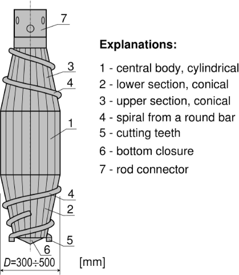
Figure 1.
Construction of the prototype DPDT drill auger according to Patent No. PL 235442 B1, [1]
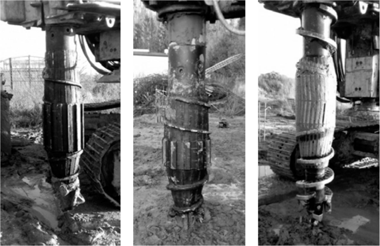
Figure 2.
Displacement pile augers tested in the research project: a) DPDT auger, b) DPDT-S auger (shortened length version), c) SDP auger, [6]
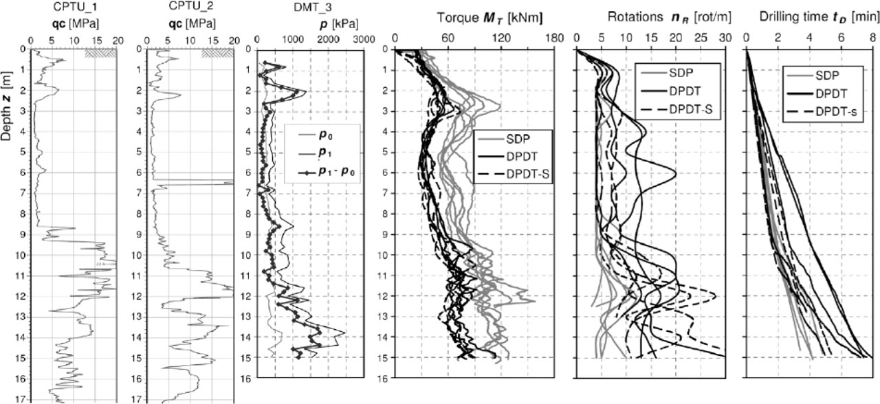
Figure 3.
A graphical comparison of the screwing parameters of DPDT, DPDT-S and SDP augers (Test plot No. 2)
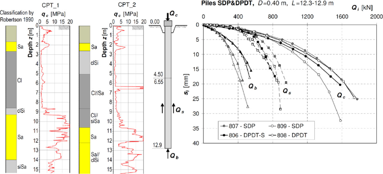
Figure 4.
Comparative results of pile load tests from experimental plot No. 2, [6]
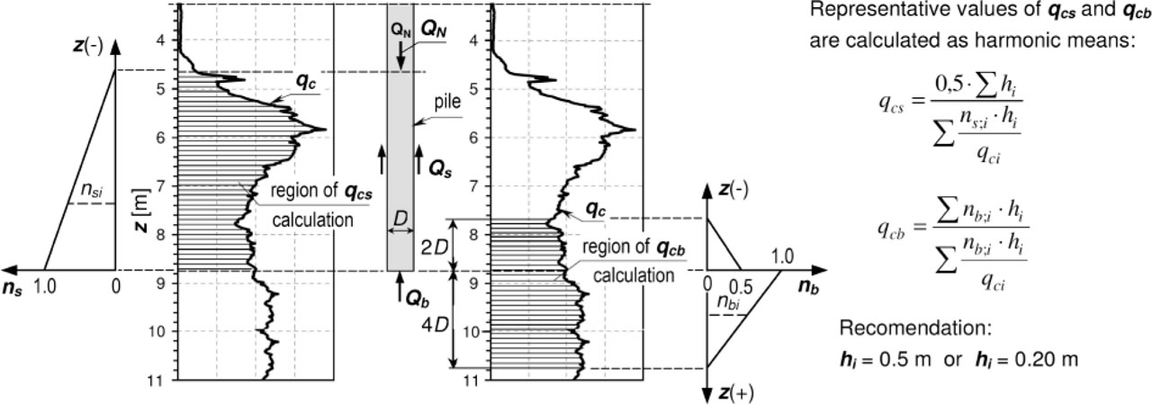
Figure 5.
Scheme for determining representative values of cone resistances qcs and qcb
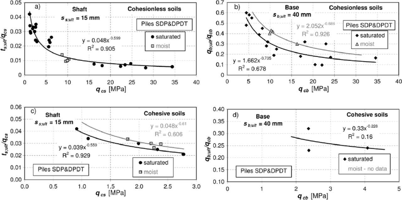
Figure 6.
Correlations between ultimate unit resistances of DPDT and SDP piles and representative CPT(U) cone resistances for cohesionless and cohesive soils
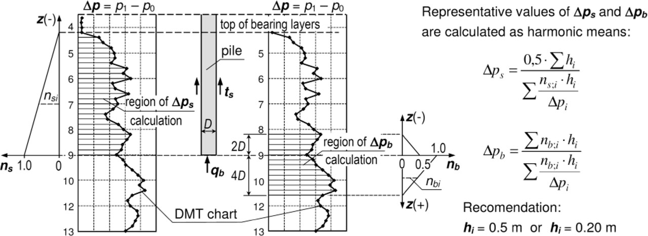
Figure 7.
Scheme for determining representative values of DMT membrane resistances ps and pb
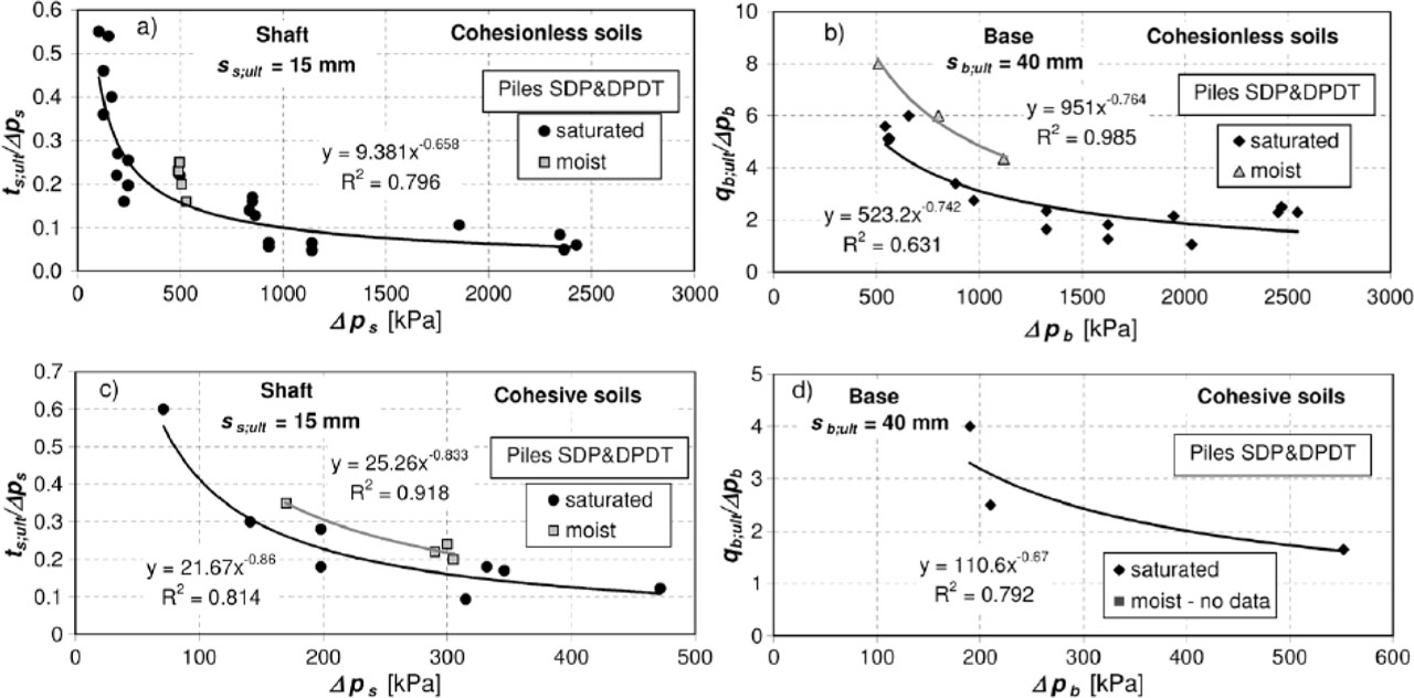
Figure 8.
Correlations of ultimate unit resistances around DPDT and SDP piles and representative DMT membrane resistances
Table 1.
List of formulas for calculating ultimate resistances ts;ult and qb;ult of the soil around DPDT and SDP piles, based on CPT(U) soundings
| Soil type | Pile shaft ts;ult [kPa] | Pile base qb;ult [kPa] | Scope of use |
|---|---|---|---|
| Cohesionless saturated | qcb = 5 ÷ 35 MPa qcs = 5 ÷ 35 MPa incl. organ. ≤ 2% | ||
| Cohesionless unsaturated | qcs = 5 ÷ 35 MPa qcb = 5 ÷ 35 MPa incl. organ. ≤ 2% | ||
| Cohesive saturated | qcs = 1 ÷ 4 MPa qcb = 1 ÷ 4 MPa incl. organ. ≤ 2% | ||
| Cohesive unsaturated | No data (A formula for cohesive saturated can be used) | qcs = 1 4 MPa qcb = 1 4 MPa incl. organ. ≤ 2% |
[i] Comments:
[ii] 1) values of qcs;i and qcb should be given in MPa
[iii] 2) reference stress should be taken as qref = 1 MPa
Table 2.
List of formulas for calculating ultimate resistances ts;ult and qb;ult of DPDT and SDP piles based on DMT soundings
| Soil type | Pile shaft ts;ult [kPa] | Pile base qb;ult [kPa] | Scope of use |
|---|---|---|---|
| Cohesionless saturated | Δps = 400 ÷ 2500 kPa Δpb = 500 ÷ 3000 kPa incl. organ. ≤ 2% | ||
| Cohesionless unsaturated | Δps = 400 ÷ 2500 kPa Δpb = 600 ÷ 3000 kPa incl. Organ. ≤ 2% | ||
| Cohesive saturated | Δps = 100 ÷ 600 kPa Δpb = 100 ÷ 1000 kPa incl. organ. ≤ 2% | ||
| Cohesive unsaturated | No data (A formula for cohesive saturated can be used) | Δps = 100 ÷ 600 kPa Δpb = 100 ÷1000 kPa incl. organ. ≤ 2% |
[i] Comments:
[ii] 1) values of Δps and Δpb should be given in kPa
[iii] 2) reference stress should be taken as pref = 1 kPa
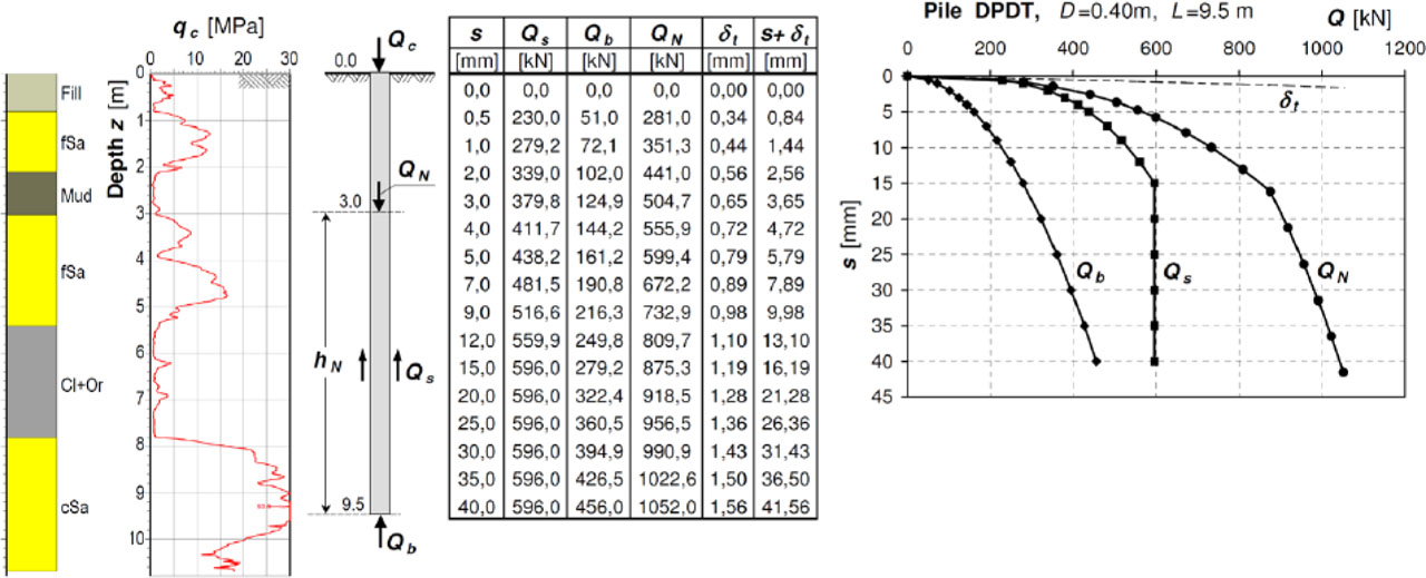
Figure 9.
An example of calculating and determining the Q-s characteristic of a DPDT pile
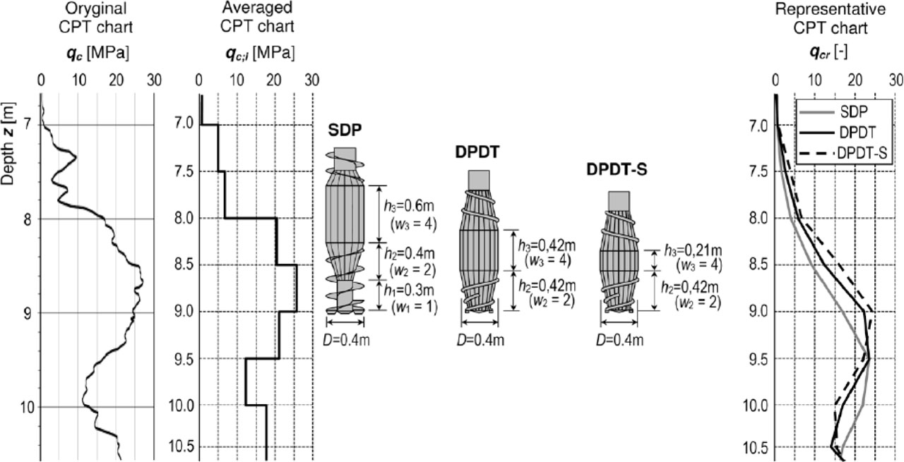
Figure 10.
Scheme for determining representative cone resistance values qcr from CPT probing graph and for individual pile auger types
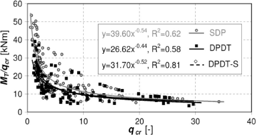
Figure 11.
Comparison of MT/qcr trend lines for all three augers from all experimental field plots
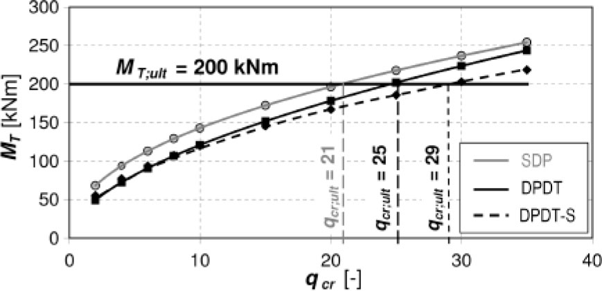
Figure 12.
Derived MT dependencies on qc;r for the tested SDP, DPDT and DPDT-S pile augers