
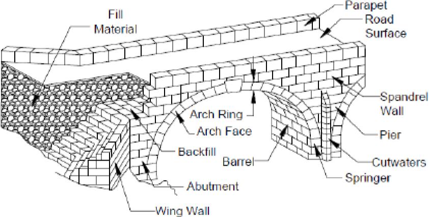
Figure 1.
Construction details of a typical historical bridge [19]
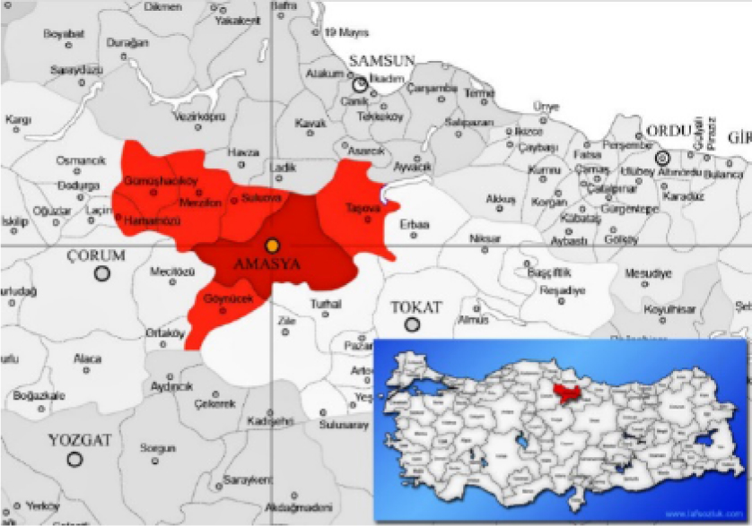
Figure 2.
Map of Turkey and location of Amasya city [35]
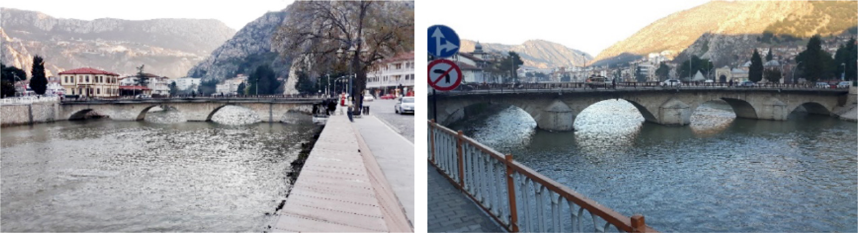
Figure 3.
Hundi Hatun Bridge – Downstream and upstream views [32]
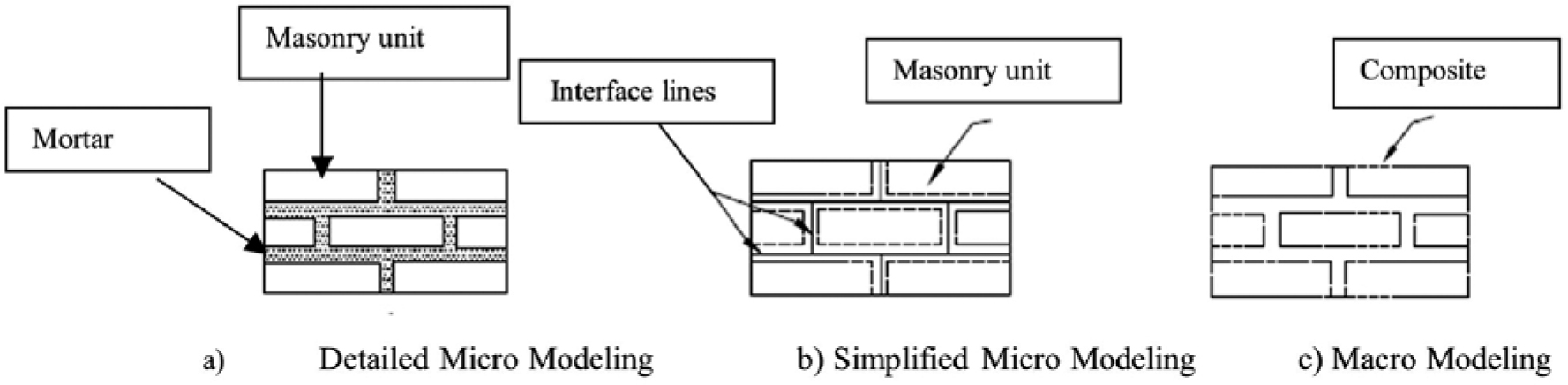
Figure 4.
Masonry structure modeling technique
Table 1.
Physical and mechanical properties of homogenized materials used in the bridge
| Bridge Region | Elasticity Modulus (MPa) | Poisson’s Ratio | Density (kg/m3) | Mean Compressive Strength (MPa) | Mean Tensile Strength (MPa) |
|---|---|---|---|---|---|
| Arches and Wing Walls | 8810 | 0.15 | 2646 | 8.810 | 0.881 |
| Fill | 800 | 0.23 | 1800 | 0.8 | 0.08 |
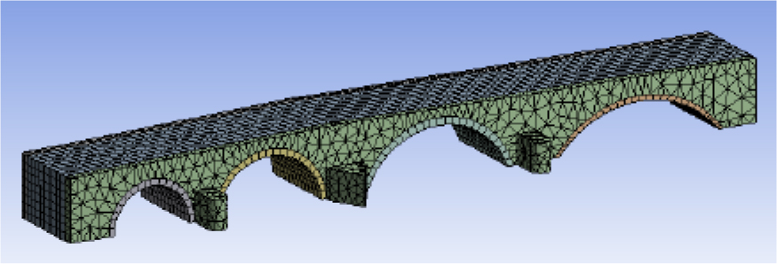
Figure 5.
Finite element model of the Hundi Hatun Bridge
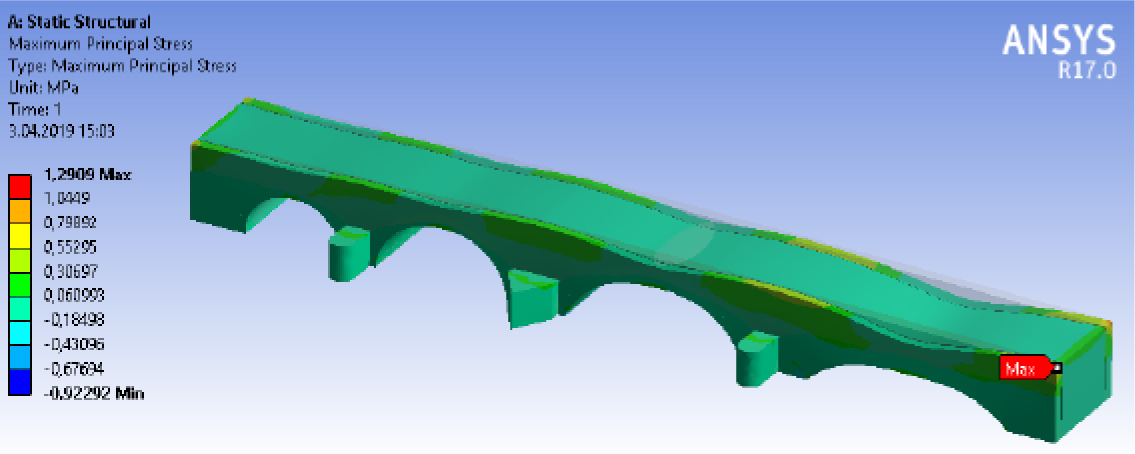
Figure 6.
Maximum principal stress distribution
Table 2.
Hundi Hatun Bridge – mass participation ratios
| Mode | Period (s) | Mass Participation Ratios | |
|---|---|---|---|
| X - direction | Y - direction | ||
| 1 | 0.10027 | 0.254380 | ~0.00 |
| 2 | 0.086250 | 0.109023 | 0.160643 |
| 3 | 0.085595 | ~0.00 | 0.228147 |
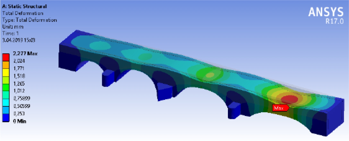
Figure 7.
Modal Analysis
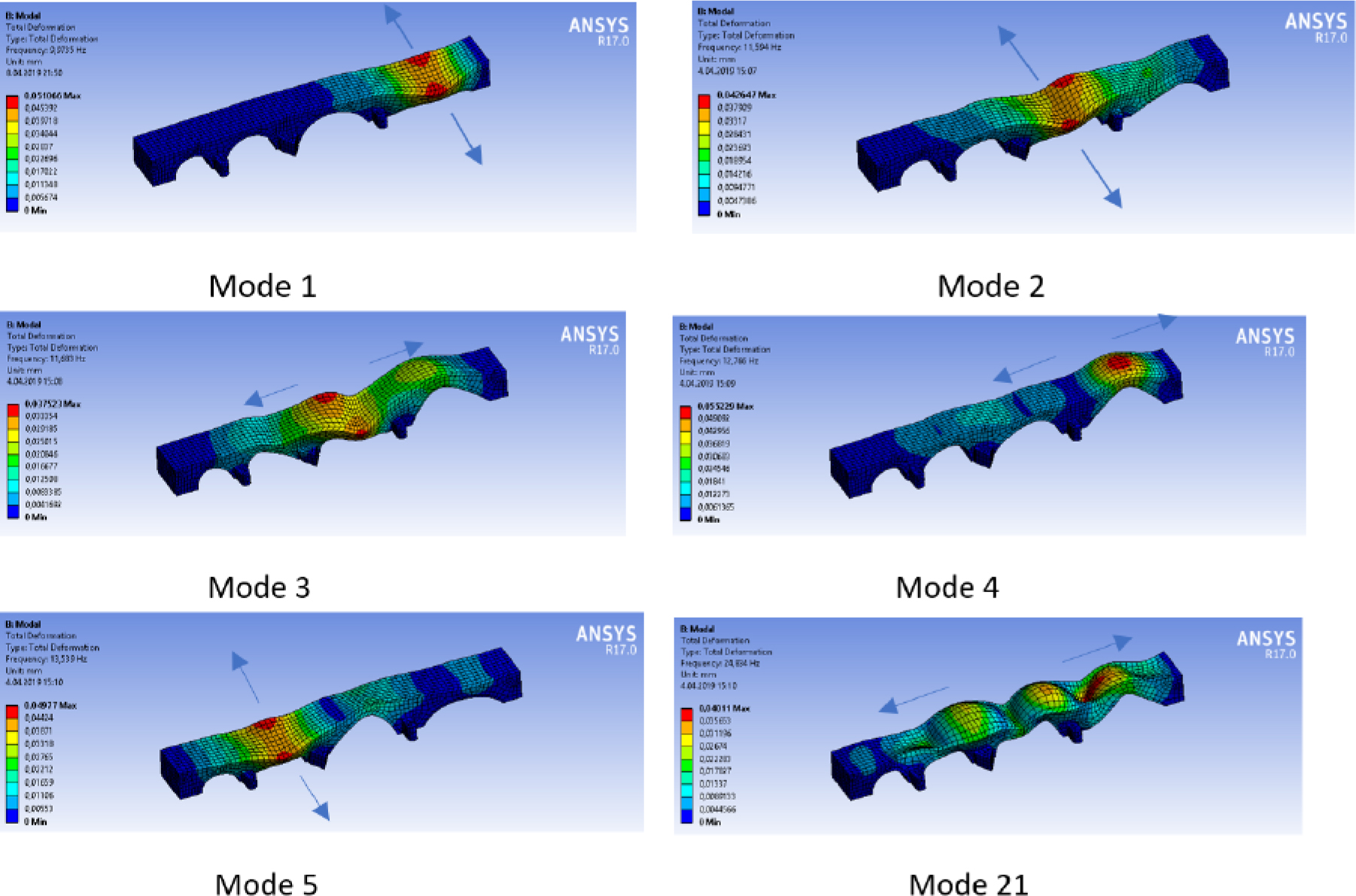
Figure 8.
Mode shapes
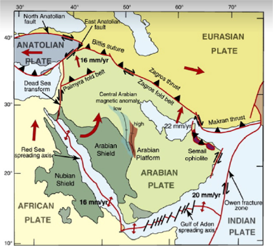
Figure 9.
Arabian plate boundaries [36]
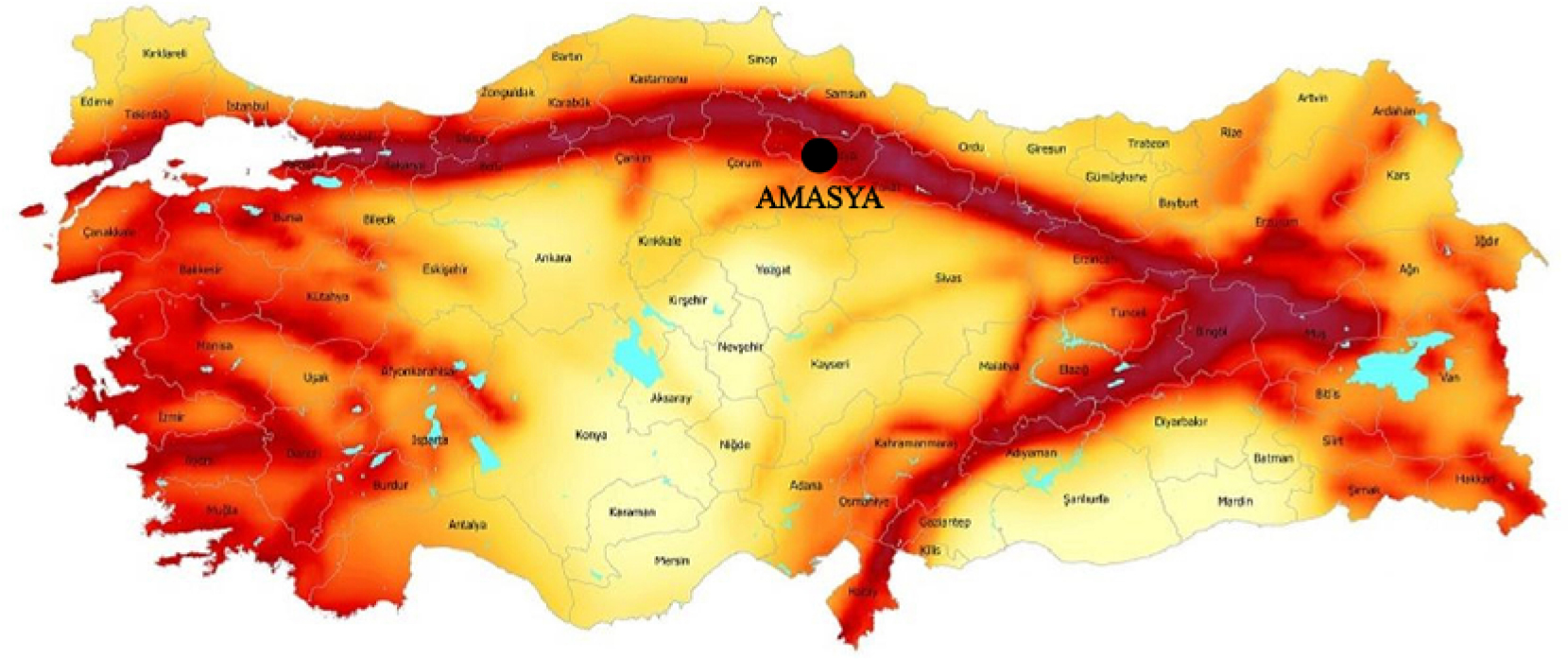
Figure 10.
Turkey’s earthquake map [37]
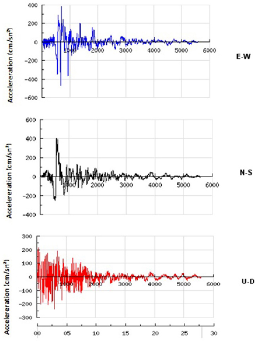
Figure 11.
The acceleration values of the 1992 Erzincan earthquake (cm/s2) [37]
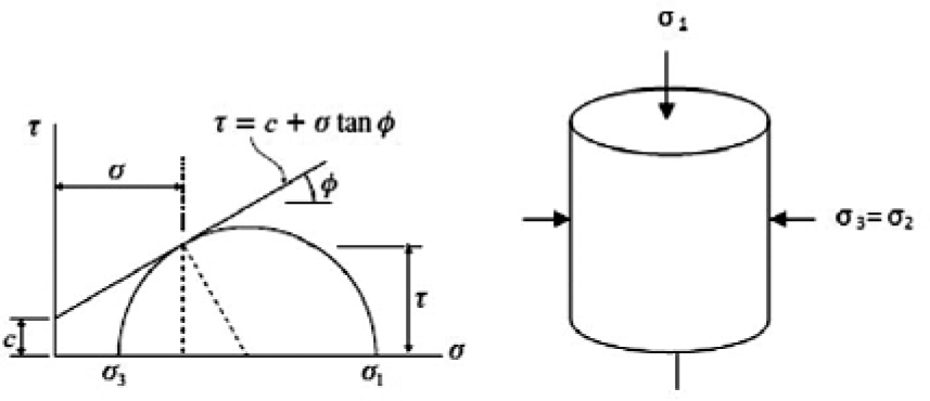
Figure 12.
The Mohr-Coulomb failure criterion [13]
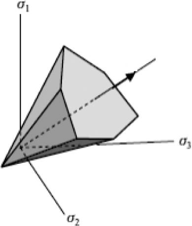
Figure 13.
The Mohr-Coulomb failure hypothesis collapse plane [13]
Table 3.
The Mohr-Coulomb material model properties for the homogenized materials used in the Hundi Hatun Bridge [15, 28]
| Bridge | Cohesion (C) (MPa) | Friction Angle (ϕ) |
|---|---|---|
| Arches and Wing Walls | 0.15 | 30 |
| Fill | 0.05 | 20 |
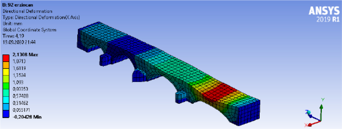
Figure 14.
X-Direction maximum deformation distribution
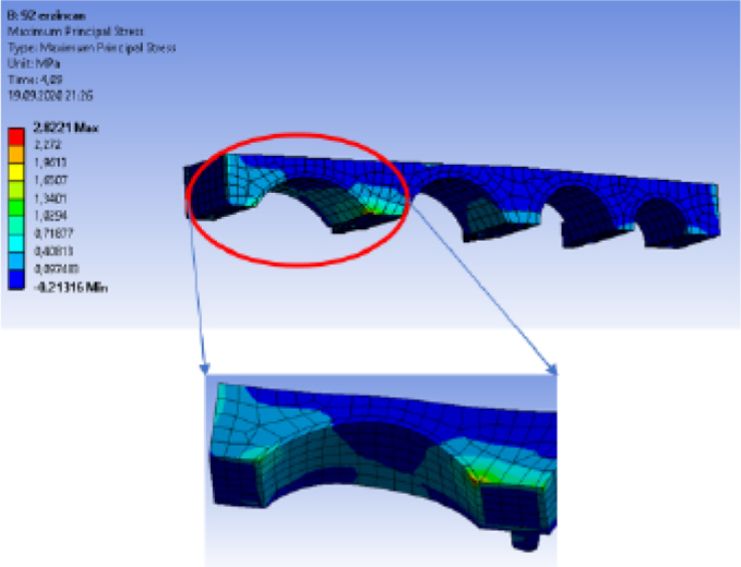
Figure 15.
1st principal stress distribution
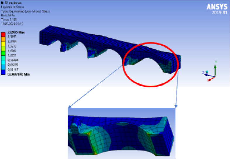
Figure 16.
Equivalent stress distribution
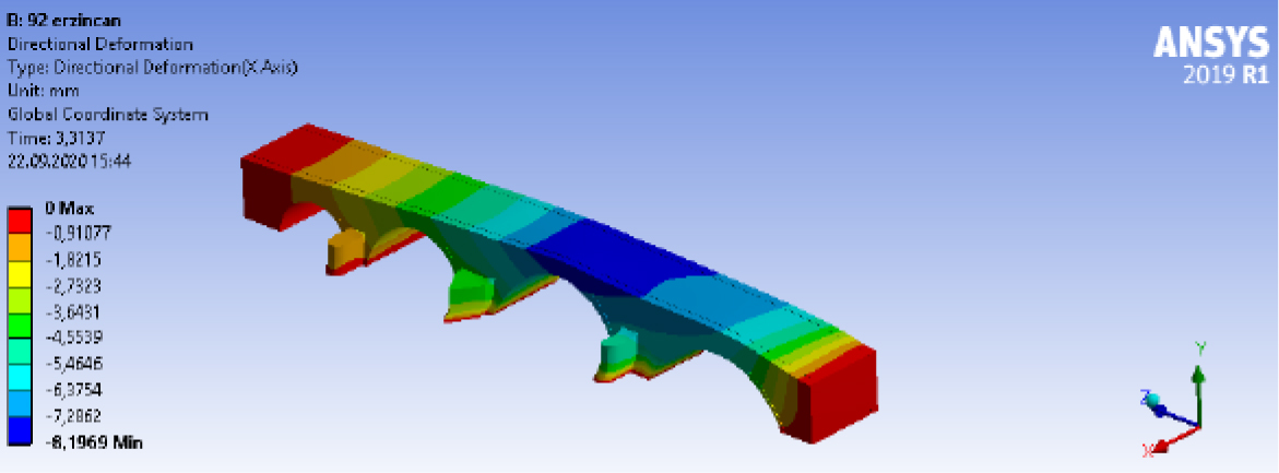
Figure 17.
Maximum x-direction deformation distribution
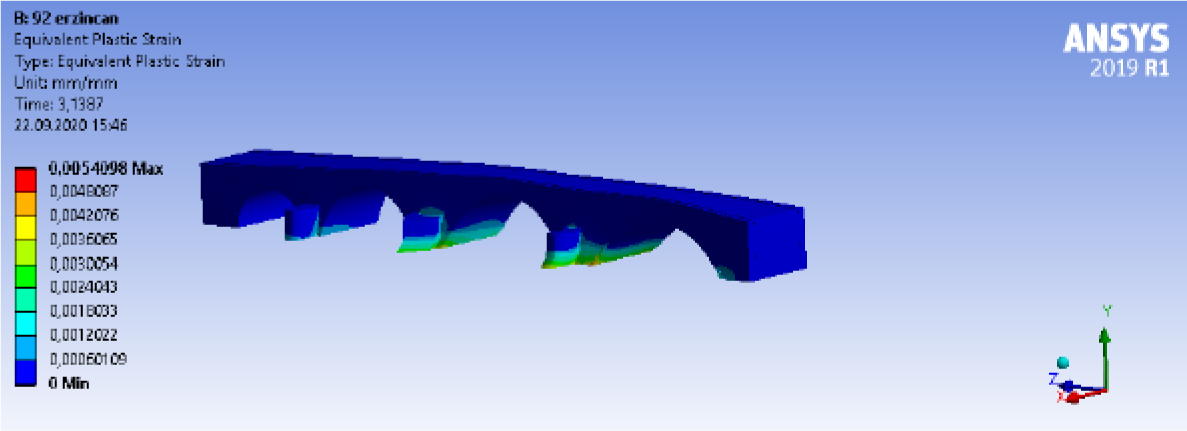
Figure 18.
Maximum plastic strain propagation
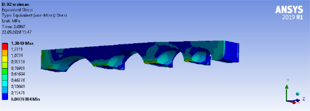
Figure 19.
Equivalent stress distribution
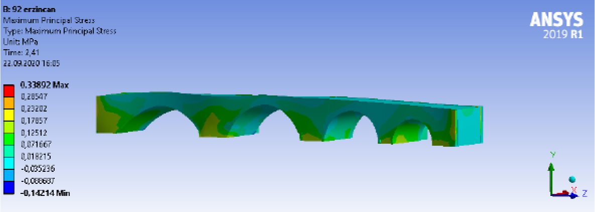
Figure 20.
1st principal stress distribution