
The energy-efficient provision of indoor comfort for buildings is one of the most important requirements for modern construction. It can be achieved in two main ways: energy-efficient engineering systems and using natural measures such as the greening of buildings.
The last group of measures provides more opportunities. The experience in using these measures is significant, starting from sod roofs, invented in prehistory (Berg, 1989). Despite this, the most limiting factor is the lack of systematic research on the positive effects.
Most of the energy-efficient engineering solutions consist of the optimally orientating buildings (Zhelykh et al., 2020), increasing the air-tightness (Corcoran & Duffy, 2019; Kuhnhenne et al., 2020) and the thermal resistance (Brunoro, 2024; Štastný et al., 2024) of the building envelopment; effective heating systems (Cholewa et al., 2018; Voznyak et al., 2021), etc.; optimizing ventilation strategies (Gładyszewska-Fiedoruk et al., 2019; Brunoro, 2024); effective inlet air treatment (Alsayah et al., 2024; Bari et al., 2024); optimizing air exchange organization (Voznyak et al., 2019; Voznyak et al., 2022); optimizing air volume control (Kim & Cho, 2022; Nassif, 2022); solar radiation protection (Muñoz-Viveros, 2022); and using renewable energy (Zhelykh et al., 2016; Shapoval et al., 2019a; Shapoval et al., 2019b; Shapoval et al., 2021; Venhryn et al., 2021; Voznyak et al., 2023). These measures are single-task solutions, which can only decrease the energy demands.
In contrast, increasing amounts of research is being devoted to all-in-one measures, such as green structures as a combination of living pants and building structures. They are solving different tasks simultaneously, including decreasing energy demands (Gioannini et al., 2018; Rey et al., 2020) and mitigating the urban heat island effect (Fallmann et al., 2014; Luthfiyyah & Widjajanti, 2019), heat insulation, and cooling effect through evaporative cooling caused by evapotranspiration; increasing the roof durability (Gioannini et al., 2018); cleaning pollution from the air (Chen et al., 2020); oxygenating the air by photosynthesis (Zhang et al., 2021); suppressing noise (Gioannini et al., 2018); effectively managing and treating rainwater (Chen et al., 2018; Zeng et al., 2019); supporting biodiversity, including pollinators (Gill et al., 2020); creating a close-to-natural aesthetic (Gioannini et al., 2018) environment, which provides mental health, calming (Nwankwo et al., 2022), eco-regulation and passive rehabilitation; inducing passive environmental education (Gioannini et al., 2018); and increasing the areas for recreation and business, including urban agriculture (Qiu et al., 2013).
Most of the works above are more qualitative than quantitative. Some of them are case studies, and the results cannot be applied broadly in most cases. Thus, optimizing such green structures is a problem requiring additional research.
In contrast to the above-mentioned works, there is a complex of multidisciplinary, quantitative and qualitative, laboratory and field research on the thermotechnical properties of grass layers revealing a significant cooling effect up to 4 K (Tkachenko & Mileikovskyi, 2018a; Tkachenko & Mileikovskyi, 2020a); solar protection (Tkachenko & Mileikovskyi, 2018b; Tkachenko & Mileikovskyi, 2020b); rainwater management (Hlushchenko et al., 2022; Tkachenko et al., 2023b; Kravchenko et al., 2024; Tkachenko et al., 2024a); rainwater cleaning (Kravchenko et al., 2024); carbon dioxide sequestration (Tkachenko et al., 2019; Tkachenko & Mileikovskyi, 2022); air cleaning (Tkachenko et al., 2019); reparation of historical places with out-of-context building (Tkachenko et al., 2024); and biodiversity (Tkachenko et al., 2023a).
Extensive green roofs that do not provide access for people usually cover the roof surface with grass and small shrubs, providing thermotechnical effects to the whole roof surface. Semi-intensive green roofs have paths for the people, which are usually covered by some pavement, which absorbs solar radiation and converts it to heat. If the roof is combined with the ceiling, the heat will pass to it and load the air-conditioning systems. The proposed solution for such roofs is to build these paths over the auxiliary premises, such as corridors, storage rooms, wardrobes, etc., which have low microclimate requirements.
This recommendation has been proposed without calculations based only on the presence of the effect. Thus, this should also be checked.
The work aims to estimate the heat distribution in green roofs with paths to ground the recommendations for planning green roofs for the maximum thermotechnical effect. The research object is green roofs combined with ceilings as the effective biotechnology of joining the building structures and living plants. The research subject is the heat transfer process inside green roofs combined with the ceiling.
To show the specifics of the heat transfer, we built a 3D model of a semi-intensive green roof fragment combined with a ceiling of a room, coated at the top by the ZinCo Perennial Garden system (ZinCo USA, Inc., n.d. a) and a ZinCo Hard Landscape system (ZinCo USA, Inc., n.d. b) path (Fig. 1, Table 1). We ignore very thin layers, such as the root barrier and the system filter, which cannot influence the heat transfer. The thermotechnical properties of most of the layers have not yet been researched. Thus, we will apply analogical materials according to Table 1.
Paths on green roofs are the heat-conductive inclusions. Such nodes cannot be analytically calculated. They should be simulated using the Fourier–Kirchhoff equation (Hojny et al., 2023). The simulation is performed using the finite element method:
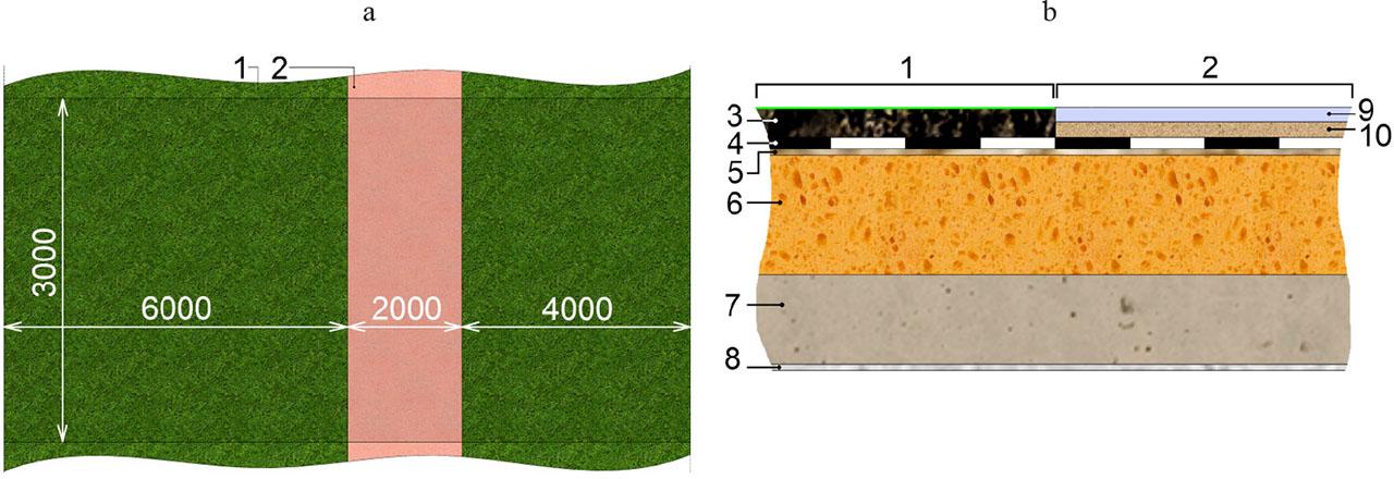
Layers
| Position in Fig. 1 | Layer | Material or analogue | Density (ρ) [kg·m−3] | Specific heat (c) [J·kg−1·K−1] | Thermal conductance (λ) [W·m−1·K−1] | Thickness (δ) [mm] |
|---|---|---|---|---|---|---|
| 3 | substratum | clayditea | 300 | 972 | 0.13 | 100 |
| 4 | drainage | polycarbonate 40a | 102.5 | 1 010 | 0.072 | 40 |
| 5 | protection | synthetic carpeta | 160 | 2 500 | 0.06 | 20 |
| 6 | insulation | polystyrene | 1 050 | 1 800 | 0.14 | 400 |
| 7 | slab | cast concrete | 2 000 | 1 000 | 1.13 | 300 |
| 8 | plaster | lightweight plaster | 600 | 1 000 | 0.16 | 20 |
| 9 | pavement | cast concretea | 2 000 | 1 000 | 1.13 | 50 |
| 10 | bedding | gravela | 1 840 | 840 | 0.36 | 50 |
Analogue.
Source: own work based on Fareniuk et al. (2014); ZinCo USA, Inc. (n.d. a); ZinCo USA, Inc. (n.d. b).
The precision of Equation (1) corresponds to the precision of the thermophysical properties of the materials and boundary conditions. The main assumptions and boundary conditions are the following. There is no contact thermal resistance between materials. Air conditioning in the room below the roof maintains constant temperature θIDA equal to 298.15 K. The ceiling surface transfers heat with constant heat transfer coefficient α equal to 8.7 W·m−1·K−1 (Hojny et al., 2023):
The path surface absorbs the convective heat (or transfers if negative) with constant heat transfer coefficient α equal to 23 W·m−1·K−1 (Hojny et al., 2023):
The path surface also absorbs solar radiation with a constant absorbance of 0.5. The solar radiation is calculated for the corresponding date and time moment. The surface under the grass has a temperature (Tkachenko & Mileikovskyi, 2020a):
The regime of the heat conduction is quasi-periodical: the outdoor temperature change during each day is to be assumed as the same by repeating the weather data of a representative day until the temperature field change on the ceiling on the final day repeats the previous one with a maximum deviation less than 0.2 K.
The sun’s movement will produce a temperature change on the outer surface of the paths, causing a thermal wave. It will attenuate in the structure’s layers due to thermal inertia and cause some heat trace on the ceiling below.
The simulation results were performed for two days: a warm day on July 11, 2024, and August 11, 2024, with moderate temperatures (Fig. 2). On both days, the path gives a trace of higher heat transfer on the ceiling (Fig. 3). Due to the thermal capacity of the concrete slab, the trace does not change from night to day.
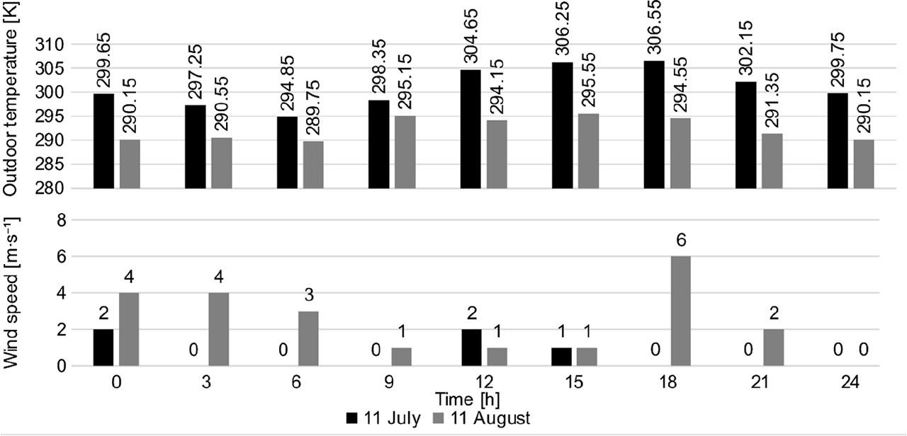
Weather conditions
Source: own work.
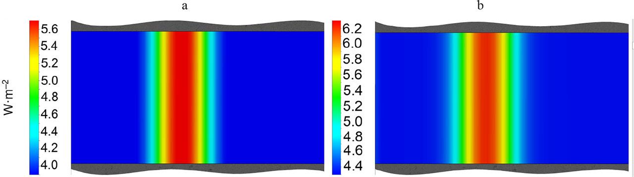
Results of simulation of heat flow density across the whole day: a – with a moderate temperature (August 11, 2024); b – warm (July 11, 2024)
Source: own work.
The heat transfer difference is 2 W·m−2 for the warm day and 1.8 W·m−2 for the moderate temperatures. This value is not very big, but is significant. For a living room of 6 × 3 m, the heat gain is 32‒36 W, which is comparable to LED illumination (up to 32 W). Thus, avoiding these unnecessary heat gains should improve the energy efficiency of air-conditioning.
Let us consider the recommendation to align, if possible, the traditional paths with the auxiliary premises such as corridors or pantries. If these rooms have no external walls, the heat gained will be distributed to other air-conditioned rooms with some lag due to thermal inertia. If this lag continues after the end of the hot period, some energy demand decrease will appear. But in a steady state, it will be minimal.
For auxiliary rooms with external walls, some heat will be dissipated. If the additional heat gains ΔΦ [W] appears, the temperature of the auxiliary room will slightly rise by Δθ [K]. If the hot period is long enough to achieve near-to-steady heat transfer, this heat will be distributed to other rooms and the environment through indoor and outdoor enclosures with a U-factor of Ui [W·m−1·K−1] and area Ai [m2]. The portion and total will be, respectively:
From Equations (6) and (7):
Thus, in steady-state mode, the dissipated part of the heat gain through external wall number i equals 0:
In energy-efficient buildings, U0 << Uj, j ≠ 0, and in most buildings, A0 < ΣAi. Thus, most heat will be kept in the building and will load the air conditioning. For example, a corridor of size 1.2 × 3 × 3 m with one external wall 1.2 × 3 m with a U-factor of 0.2 W·m−1·K−1 and internal walls with a U-factor of 2.7 W·m−1·K−1 in a steady state will dissipate to the environment only 0.92% of the additional gains.
It is possible to conclude that aligning the roof paths half-measure, which can mitigate the additional consumption by thermal inertia. We should therefore find stronger measures.
There are alternative options, which can produce the maximum effect based on planting the paths: using plant-permit pavement analogous to eco-parking, makes it possible to plant on pathways, or barefoot-in-dew systems such as ZinCo Soft Landscape with a denser substrate. Walking on lawns is a common European trend, which promotes more natural conditions close to the wild nature. In addition to the thermotechnical effect of covering all surfaces with cooling plants, it soothes and supports rest, and the rainwater drainage and retention abilities will increase through activation of the whole area. For green roofs with a lightweight substratum, the “virtual” paths with a denser substratum should be definitively highlighted by a noticeable difference in the appearance of the grass.
In both cases, a special grass should be planted for walking: perennial ryegrass (Lolium perenne), red fescue (Festuca rubra), meadow fescue (Lolium pratense), bluegrass (Poa pratensis), or clovers (Trifolium sp.). We did not see such innovative “green path” solutions on available green roofs.
Another possibility is using pavements with maximum reflectivity (cool roof). This solution has a disadvantage: it requires regular cleaning because dust and dirt, which are common on paths, absorb solar radiation.
The literature review shows that there is not enough research on the positive effects of green roofs to make recommendations for aligning green roof design and space-planning solutions. The simulation of a semi-intensive green roof with the ceiling of the room below combined with a roof path shows that the path induces a trace of higher heat transfer on the ceiling. The difference in the density of the heat flow below the path and the grass is not huge but is still significant, as it varies in the range of 1.8‒2.0 W·m−2. Calculations show that such alignment of the paths above the auxiliary premises is a half-measure that operates almost due to inertia and lags in heat flows. Better solutions, which are innovative for green roofs, allow planting on the paths – from plant-permit pavement analogous to eco-parking and barefoot-in-dew systems such as ZinCo Soft Landscape with a denser substrate. It is necessary to use grass that can be walked on – perennial ryegrass (Lolium perenne), red fescue (Festuca rubra), meadow fescue (Festuca pratensis, Lolium pratense), bluegrass (Poa pratensis), or clovers (Trifolium sp.). In the future, the authors plan to simulate the influence of joints and other linear and point inclusions on the thermal performance.