
Humans commonly suffer with many diseases because of food having excess quantity of salt and sugar. Limited practices have been taken to overcome the situation. A drying technique is given by Gartley (2011) to compute the salt in the soil by estimating the electrical conductivity of the soil. A coaxial probe has been utilized through microwave measurement method to detect the dielectric properties of pure water and saline water by Gadani et al. (2012). However, these techniques of detecting salt are tedious. The system advancement cost of these methodologies is high.
The dielectric properties of the water change, when the salt and sugar are dissolved in the water (Cheng et al., 2014b). The variation in the dielectric properties of solution with different concentrations of salt and sugar causes the changes in the properties of radio frequency (RF) signals. Antennas are commonly used in wireless communications for transmitting and receiving electromagnetic (EM) signals. Antennas and electromagnetic waves can also be used as sensors. Makwana and Ghodgaonkar (2013) used the dielectric resonator antenna (DRA) as radio frequency identification (RFID) tag for human identification. Kot et al. (2014) presented the feasibility of using EM waves for identifying objects behind the walls. Microstrip patch antennas are suitable in many applications such as agriculture, medicine, sensor, communication, etc., as these antennas show favorable characteristics like low profile, light weight, easy fabrication, etc. In the present days, wireless correspondence frameworks and expanding of different remote applications, more extensive data transfer capacity or wider bandwidth, multi-band and low-profile antennas are in incredible interest for both business and military applications. Low gain and narrow bandwidth are the major limitations of the microstrip antennas (Balanis, 2005; Garg et al., 2001). DGS technology helps to improve the performance of the microstrip patch antennas. In DGS technology, the ground plane of the microstrip antennas is made defected by incorporating slots (Khandelwal et al., 2017; Lalitha Bhavani Konkyana and Alapati Sudhakar, 2019). By using DGS, Ngobese and Kumar (2018) proposed a high gain antenna array. Nhlengethwa and Kumar (2020) used the concept of DGS to enhance the gain of the microstrip antenna. The dual-band microstrip patch antennas using DGS are designed in the studies of Mabaso and Kumar (2018) and Mabusha and Kumar (2020). A triple-band microstrip patch antenna is proposed by Mabaso and Kumar (2019). The size of the microstrip antenna is reduced using DGS in the study of Sanega and Kumar (2020). The bandwidth of the microstrip patch antenna is enhanced using DGS by Mumin et al. (2018). Using DGS, the microstrip antennas are designed for ultra-wideband (UWB) applications (Kumar, 2017, 2019; Dharmarajan et al., 2019, 2020). The microstrip antenna with DGS was designed for dual polarization by Ghosh et al. (2011). Yadav et al. (2019) proposed the microstrip antenna with DGS for circular polarization. The multiple input multiple output (MIMO) antennas with DGS were proposed by Pandit et al. (2018) and Nigam et al. (2020).
Microstrip antennas can also be utilized to detect salt and sugar in the water as the dielectric properties of the solutions are different for different concentrations of salt and sugar in water. Cheng et al. (2014a) proposed the salinity and sugar detection system for detecting salt and sugar in water. The rectangular, square, and circular patch antennas were used to detect salt and sugar concentration in the water. Rahman et al. (2018b) proposed a salinity and sugar detection system using a Psi-shaped microstrip patch antenna. Islam et al. (2018) proposed a salt and sugar detection system for detecting salt and sugar concentration in water using a crescent-shaped microstrip patch antenna. Rahman et al. (2018a) proposed a tuning fork-shaped microstrip patch antenna-based salt and sugar detection system for detecting salt and sugar concentration in water.
A compact microstrip patch antenna to detect salt and sugar concentration in the water is proposed in this paper. The proposed antenna for salt and sugar detection utilizes the concept of DGS for reducing the size of the antenna. Moreover, as the slots in the ground plane also behave like resonating elements, so it enhances the performance of the salt and sugar detection system as the concentration of salt and sugar affects from both sides, i.e. patch and ground plane. The proposed antenna is compared with the existing antennas used for salt and sugar detection. It is observed that the proposed antenna for salt and sugar detection is compact in size and the cost of the antenna is low as antenna is fabricated on FR4 substrate. The experiments for detecting the concentration of salt and sugar in the water are performed. The experiments confirm that the proposed antenna can be used to detect salt and sugar concentration and the antenna is also suitable for 2.4 GHz wireless applications. Rest of the paper is organized as follows. The second section presents the design, geometrical configuration, and dimensions of the proposed antenna. The antenna parameters and the measurements for detecting salt and sugar concentration in water using the proposed antenna are discussed in the third section. The conclusion of the work is given in the fourth section.
Antenna geometry and design
A rectangular patch is widely used patch as it is easy to analyze using the transmission line model and cavity model (Balanis, 2005). The antenna dimensions are calculated using the transmission line method of analysis. The configuration of the proposed compact microstrip patch antenna is shown in Figure 1. The top view, side view, and bottom view of the antenna are depicted in Figure 1A, Figure 1B and Figure 1C, respectively. The rectangular microstrip patch is designed on a FR4 substrate. The width W of the patch for resonant frequency freso, substrate thickness h and substrate dielectric constant εr is calculated by using the following equation (Balanis, 2005):
(1)where c is the speed of light. The fringing effect decreases the dielectric constant of the material and after taking this effect into account, the effective dielectric constant εreff is calculated by using the following equation (Balanis, 2005):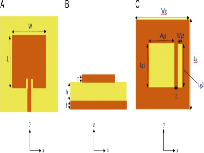
Figure 1:
Antenna geometry: (A) top view, (B) side view, and (C) bottom view.
The fringing effect increases the length of the patch by ΔL on each side. So, the actual length of the patch L is computed by using the following equation (Balanis, 2005):
(3)where Leff is the effective length of patch due to fringing field and is given by the following equation:The increment in the length of patch on each side due to fringing field is given by the following equation (Balanis, 2005):
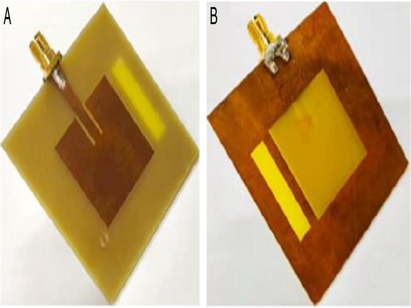
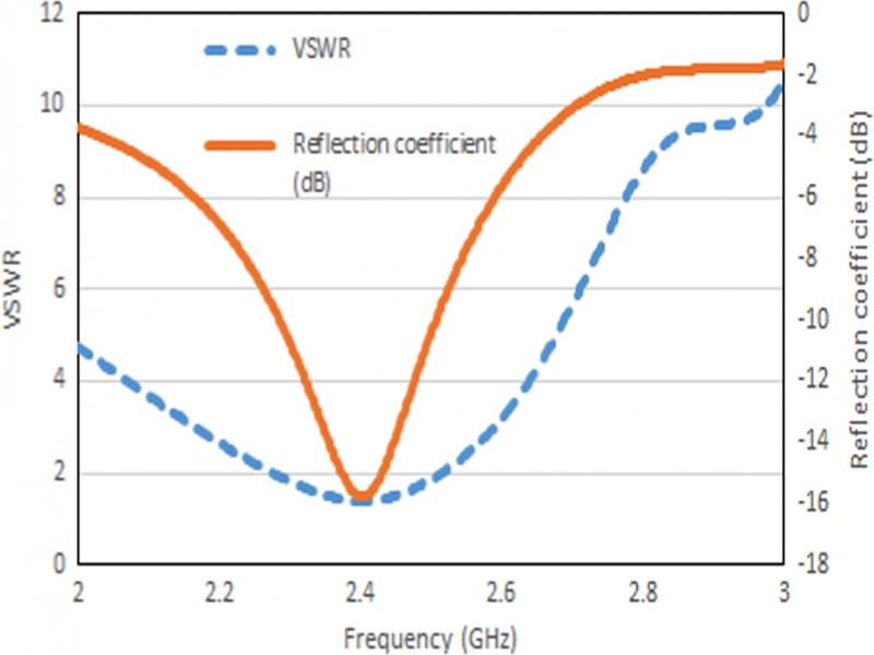
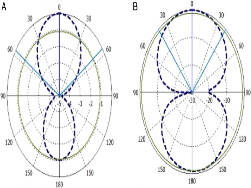
To improve the antenna performance and to reduce the size of the antenna, the two slots are cut in the ground plane as shown in Figure 1C. The slots in the ground plane reduce the reflection coefficient of the structure and improve the antenna performance. The proposed structure is simulated and optimized using CST microwave studio. The optimized dimensions are given in Table 1. In this table, L, W, Lg, and Wg are the length of the patch, width of the patch, length of the ground plane and width of the ground plane, respectively. Lg1 and Wg1 are the length and width of the slot positioned at the center in the ground plane. Lg2 and Wg2 are the length and width of the slot positioned at a gap distance 2.5875 mm from the center slot in the ground plane. The DGS is resonating in nature and by adjusting the dimensions of the slots in the ground, the resonant frequencies are varied and the size of the antenna is reduced. The dimensions of the antenna with DGS and without DGS for the same substrate parameters and same resonant frequency are shown in Table 2. It can be observed that slots in ground plane provide a reduction in the antenna area by 21.5%. The antenna with DGS is fabricated for the measurements. The fabricated compact microstrip patch antenna is shown in Figure 2. The top layer and bottom layer of the fabricated antenna are shown in Figure 2A and Figure 2B, respectively.
Table 1.
Optimized dimensions of the compact antenna.
| S. No. | Dimensional parameter | Values | ||
|---|---|---|---|---|
| 1 | L | 25.65 mm | ||
| 2 | W | 25.65 mm | ||
| 3 | Lg | 51.3 mm | ||
| 4 | Wg | 51.3 mm | ||
| 5 | Lg1 | 25.65 mm | ||
| 6 | Wg1 | 25.65 mm | ||
| 7 | Lg2 | 24.41 mm | ||
| 8 | Wg2 | 5.1525 mm | ||
| 9 | g | 2.5875 mm | ||
| 10 | h | 1.5 mm | ||
| 11 | t | 0.035 mm | ||
| 12 | εr | 4.3 |
| S. No. | Antenna type | Area of patch | Area of ground plane | |
|---|---|---|---|---|
| 1 | Antenna without DGS | 838.1 mm2 | 3,352.4 mm2 | |
| 2 | Antenna with DGS | 657.9 mm2 | 2,631.7 mm2 |
| S. No. | Slot length | Resonant frequency | VSWR (at 2.4 GHz) | |S11| (at 2.4 GHz) |
|---|---|---|---|---|
| 1 | 24.95 mm | 2.466 GHz | 1.514 | −13.433 dB |
| 2 | 25.65 mm | 2.402 GHz | 1.389 | −15.768 dB |
| 3 | 26.45 mm | 2.336 GHz | 1.68 | −11.913 dB |
| 4 | 28.95 mm | 2.082 GHz | 4.624 | −3.817 dB |
| Radiation efficiency | Total efficiency | Max. gain | Max. directivity | |
|---|---|---|---|---|
| −1.84 dB | −1.97 dB | 2.12 dB | 3.95 dBi |
| S. No. | Frequency | Return loss (concentration: 20%) | Return loss (concentration: 50%) | Return loss (concentration: 80%) |
|---|---|---|---|---|
| 1 | 2.38 GHz | 23.271 dB | 21.017 dB | 13.334 dB |
| 2 | 2.56 GHz | 23.757 dB | 20.54 dB | 13.281 dB |
| 3 | 2.72 GHz | 24.582 dB | 19.84 dB | 13.046 dB |
| 4 | 2.86 GHz | 23.253 dB | 17.095 dB | 11.691 dB |
| S. No. | Frequency | Return loss (concentration: 20%) | Return loss (concentration: 50%) | Return loss (concentration: 80%) |
|---|---|---|---|---|
| 1 | 2.38 GHz | 23.558 dB | 19.123 dB | 13.022 dB |
| 2 | 2.56 GHz | 24.251 dB | 22.012 dB | 13.223 dB |
| 3 | 2.72 GHz | 24.097 dB | 21.293 dB | 13.144 dB |
| 4 | 2.86 GHz | 22.044 dB | 17.272 dB | 11.962 dB |
| Reference | Antenna type | Center frequency | Dimensions of the antenna | Substrate parameters |
|---|---|---|---|---|
| Cheng et al. (2014a) | Rectangular microstrip antenna | 2.45 GHz | 0.47λ0 × 0.388λ0 | εr = 2.2, h = 1.575 mm |
| Cheng et al. (2014a) | Circular microstrip antenna | 2.45 GHz | 0.465λ0 × 0.465λ0 | εr = 2.2, h = 1.575 mm |
| Cheng et al. (2014a) | Square microstrip antenna | 2.45 GHz | 0.529λ0 × 0.529λ0 | εr = 2.2, h = 1.575 mm |
| Rahman et al. (2018b) | Circulated psi-shaped patch | 16 GHz | 1.28λ0 × 0.96λ0 | εr = 2.2, h = 1.57 mm |
| Islam et al. (2018) | Crescent-shaped microstrip antenna | 10.6 GHz | 1.13λ0 × 0.777λ0 | εr = 4.6, h = 1.6 mm |
| Rahman et al. (2018a) | Fork-shaped patch | 9.5 GHz | 0.76λ0 × 0.57λ0 | εr = 2.2, h = 1.57 mm |
| Proposed method | Rectangular microstrip antenna | 2.4 GHz | 0.41λ0 × 0.41λ0 | εr = 4.3, h = 1.5 mm |