Nomenclature
- AC
alternative current
- C
the cumulative power consumed by the combination
- C1
the cumulative power consumed by the combination when no motion detected
- C2
the cumulative power consumed by the combination when motion detected
- DC:
direct current
- K
the decision indicator
- MCU
microcontroller unit
- r
the power consumption of the reader
- R
the cumulative power consumed by the reader
- RC
the reliability of combination
- Ri
reliability of system component
- RI
the reliability of intermediate
- RR
the reliability of the reader
- Rsys
reliability of a system
- RFID
radio frequency identification
- s
the power consumption of the sensor
- S
the cumulative power consumed by the sensor
- PIR
pyroelectric infrared
Radio frequency identification is a technology for collecting and diffusing information through radio waves, it is composed of four parts: tag, reader, database, and the backend, where the retrieved data are exploited in a planned action (Bing et al., 2017; Weinstein, 2005; Williams et al., 2019; Zumsteg and Qu, 2018). It can be classified according to the energy source of the tags: the active tags have an embedded battery; the passive tags are powered through electromagnetic waves of the reader, whereas the semi-active tags have an embedded power supply only for the integrated circuit, as the antenna gets the energy from the reader. RFID usage is very common, especially in big corporations with large facilities like shipping companies that have big storage units or even hospitals, which illustrates the effectiveness and easiness that this technology adds to tracking and managements.
Usually, electronic devices have two modes: the active or the ‘in-use’ mode, where they consume electricity while executing their main functions, and the non-active mode, where they are not in-use or unplugged and obviously they do not consume electric power. But there are devices that can be in a third mode besides the previous two, called the standby mode, in which the device is not in-use but it still consumes power at idle. Although there is no official definition from the International Standards Organization (ISO), the standby power can be defined as the power consumed by electronic devices while switched-off or not executing their primary role (McGarry, 2004).
In the case of the RFID reader, the three modes can be defined as follows: the active mode is when the reader is communicating with one or more tags, the non-active mode is when the reader is unplugged from the energy source, the third mode is when the reader is kept-running, drawing energy without being in communication with a tag (waiting state).
When the RFID reader is in any mode other than the unplugged, its electromagnetic waves cover all of its range. Since its work frequency, within the radio field, is classified under the category 2B (possibly carcinogenic) by the International Agency for Research on Cancer (IARC) (Fields et al., 1999; Costea et al., 2014), many disputes were raised about its health implications. Although these claims are unsettled yet, it is certain that the radio waves can result in electromagnetic interferences which may interrupt other equipment workflow (Cheng and Prabhu, 2009; Miclaus et al., 2009; Pous Solà et al., 2010; Van Der Togt et al., 2008; Astaneh and Gheisari, 2018). Therefore, in an environment preoccupied with electronic devices, optical-based motion sensing technology is visualized as a key solution against interference of other equipment during idle time.
Motion sensors are widely used in several indoor and outdoor activities like opening a door automatically or switching on/off public lights and surveillance cameras (Kroeger et al., 2012; Tan, 2019; Tsai et al., 2011; Hernandez and Sallis, 2019). All of these systems are called ‘smart’ because of their ability of automatically executing an intended task, triggered by a motion sensor. This can be extended to smart buildings and environments (Ling, 2015; Sovacool and Rio, 2020; Aman and Anitha, 2017).
Several phenomena are exploited in detecting motion such as the optical, microwave, and acoustic (Khan et al., 2019; Micko, 2008; Lvov et al., 2018; Bakhsheshi et al., 2019; Moghavvemi and Seng, 2004). One of the very commonly used sensors is the pyroelectric infrared-based motion detector (PIR sensor), which is a passive sensor, its technology mainly based on detecting the heat energy emitted from the moving object in form of radiations, as this heat energy varies following the moving object’ temperature. So, basically the PIR sensor-based devices identify this temperature’ difference as a detected motion, which is exploited then, in triggering actions or for recording purposes.
In general, the RFID system is not power greedy, but in big facilities with large buildings, deploying a network of multiple readers can significantly affect the electricity bill in the long run. The literature shows a remarkable lack of research in this aspect, the only proposal addressing this issue was made by T. B. Austin et al. (Moghavvemi and Seng, 2004), through an integrated motion sensor-based RFID reader design. However, despite the fact that the phenomenon-based operating mechanism of the motion sensor is not specified, there are some exposed challenges obstructing the adoption of this reader, raising mainly from being a built-in design. First, its set-up cost is significantly high for the firms already running a network of RFID systems, as they need to replace all the existing readers with the new ones. Moreover, it has a higher maintenance complexity degree, meaning that any potential sensor failure, which will cause the reader to stop working, needs to be repaired by qualified maintenance personnel. This can result in an important inconvenience for the institutions that does not have an internal maintenance department, as they have to search for a specialized external servicing, which may even increase the downtime due to the associated procedural arrangements. Besides, it is obvious that upgrading to this reader is not always profitable, as it might have a reverse effect on power saving in heavily busy work spaces, due to the sensor and the reader being both constantly active rather than the reader alone, which leads to ask the question: How busy can an environment be while still being worthy of the upgrade? This remains a quite intractable question in the absence of clear indices reflecting the upgrade power effectiveness in relation to the busyness of the environment, especially that the literature provides no guidelines in this regard. Therefore, in this work, first, we attempt to address this matter through the development of a reliable decision support protocol to assess the upgrade’ feasibility in terms of power efficiency. Next, we investigate the different possibilities for inserting a motion sensor, in an RFID system, with the aim of identifying the optimal integration structure, in order to bypass the previously discussed adoptability challenges. Then, we conduct an empirical study to evaluate the energy consumption of the identified integration options compared to the regular RFID system, before finally, executing the developed decision support protocol to demonstrate its applicability. The flowchart of the proposed methodology is illustrated in Figure 1.
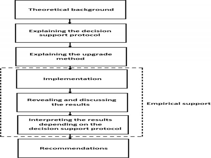
Figure 1:
Research methodology flowchart.
This paper is organized as follows: in the second section, we explain the proposed decision-support protocol along with the proposed structure of incorporating a motion sensor into the RFID system, after discussing the different integration possibilities. In the third section, we reveal and discuss the result of an empirical study, reviewing the power-efficiency of the identified motion sensor-based RFID systems, compared to the ordinary RFID system. Finally, we present our concluding remarks along with some research perspectives.
Material and method
The proposed decision support protocol
This proposed decision support protocol is set to be considered when adopting any combination involving a motion sensor, aimed at reducing power consumption, in order to assure that, during a defined period (usually 24 hr), the cumulative power consumed by the combination is less than the power consumed by the reader used alone, which reflects the feasibility of the combination in saving energy.
The protocol is divided into two parts:
Part one: determining the power consumption, during a defined period for each of the reader, the motion detector and their combination.
Part two: verifying the set condition to check the upgrade worthiness.
Part one
We denote r, s, and c, corresponding to the power consumption (expressed in watt) of the RFID reader, the motion detector, and their combination, respectively (Figure 2).
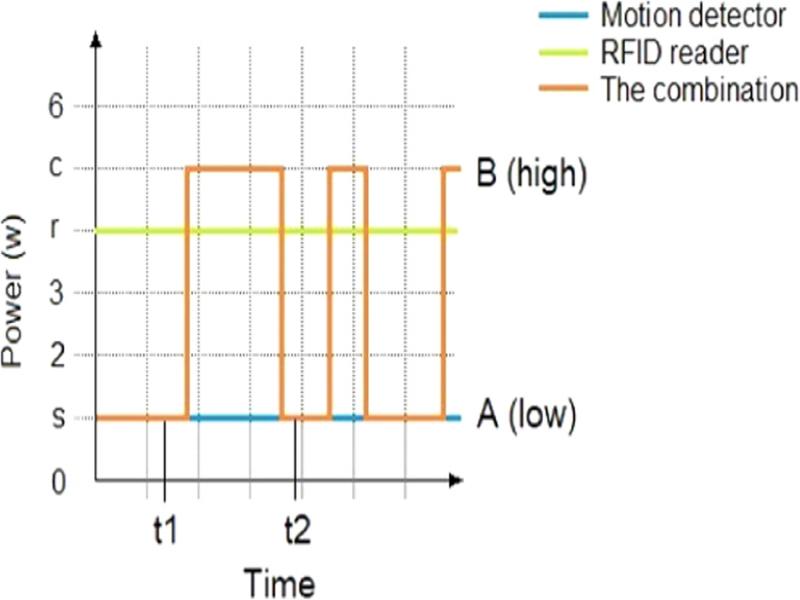
Figure 2:
Illustrative representation of power consumed by RFID reader, motion detector, and their combination.
During a period of time [t1;t2], the power consumed by the PIR sensor (S) is (Austin et al., 2014):
(1)and the power consumed by the RFID reader (R) is (Austin et al., 2014):The power consumed by their combination (C) is identified following two states: low (A) and high (B) (Figure 2). The first state (A) refers to ‘no motion detected’, which means only the PIR sensor is consuming power. This can be modeled, according to Equation (1), by:
The second state (B) refers to ‘motion detected’, which means both the PIR sensor and the RFID reader are consuming electric power. This can be modeled by combining Equations (1) and (2) such as:
Each of the above states can occur only independently and never simultaneously, i.e. at the same moment we have either C = C1 or C = C2, exclusively.
Thus, during a period of time [t1;t2] implying both states, the power consumed by the combination can be deduced from Equations (3) and (4) such as:
Part two
After determining the power consumed by both the reader alone and the combination involving a PIR sensor, we can calculate the decision indicator (K) by using Equation (6) and referring to Equations (2) and (5), which allows us to identify the best option in terms of power efficiency such as:
(6)If K > 0, the combination is worthy for improving the power consumption.
If K = 0, the combination is not worthy for power saving, but it might be dedicated for other tasks; such as reducing electromagnetic interferences possibility.
If K < 0, the combination is onerous and wasteful.
The above protocol was initially designed for the case above (motion sensor and reader). However, it can be generalized later for any motion sensor-based device that aims to reduce power consumption.
The motion sensor-based smart RFID system
Since this combination is aimed at saving energy, the PIR sensor is the first option to consider, as it provides the lowest standby power consumption compared to other motion sensors, and it is, therefore, widely deployed.
The combination has two parts hardware and framework, described as follows.
Hardware
This motion sensor-based smart system can be achieved in two ways, as shown in Figure 3. The first way (Type A) is the built-in way, as applied in Shenkman (2006), whereas the second way (Type B) suggests using an external intermediate to trigger the RFID reader. This intermediate can be a simple relay or a thyristor-based or mostly an MCU (microcontroller unit). The PIR sensor detects whether a possible tag carrier is approaching or not. Based on that, the MCU turns the reader on/off, through the relay.
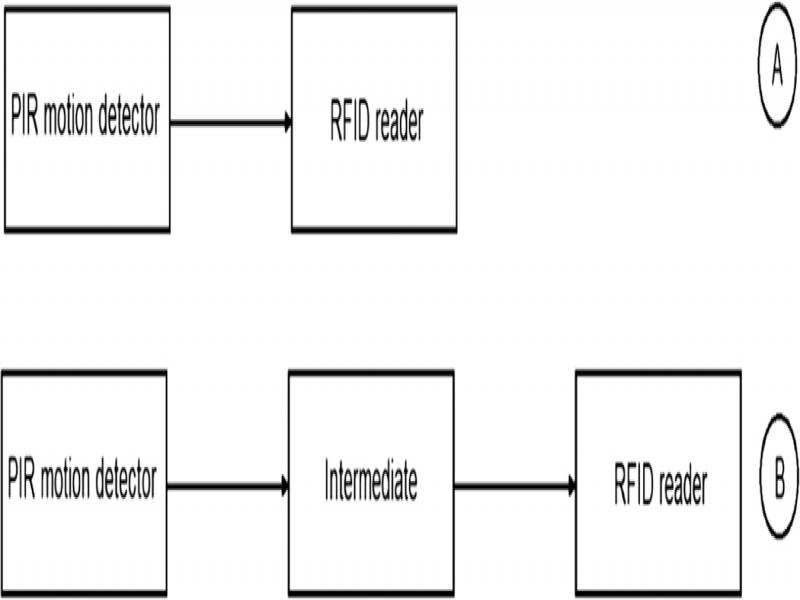
Figure 3:
The options of integrating the motion detector.
Figure 4 describes the combination that includes the MCU. This enhanced smart system is adapted for large facilities, so they can mount the upgrade directly on the top of their existing ordinary RFID management system without having to replace any component.
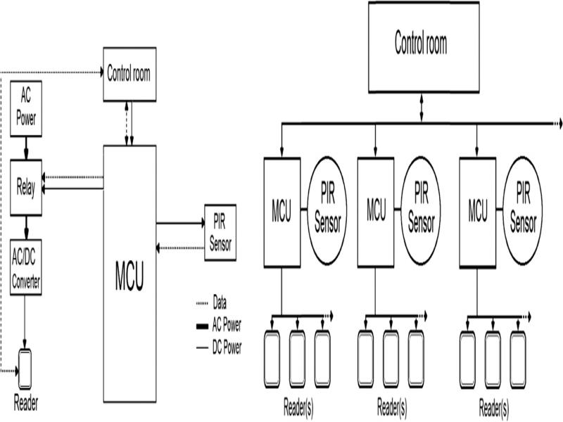
Figure 4:
Block diagram of smart RFID system and a grid of smart RFID systems.
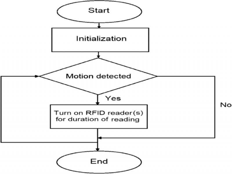
Figure 5:
Program flowchart of PIR sensor-based RFID system.
The inner AC/DC converter acts as a power supply for the RFID reader, as it requires DC voltage input; therefore, in large facilities with a grid of multiple RFID readers, the use of numerous converters can be very wasteful, given that they drain more power than the main devices, at low currents (Tan, 2019). Therefore, it is much worthier to power the MCUs by linking them to the server in the control room, rather than adding external converters, whereas the PIR sensor and the relay are powered by connecting them to the MCU. Thus, avoiding the converters’ onerous power consumption.
As illustrated in Figure 4, in a grid that contains a number of PIR sensors-based RFID systems, we have two levels (Fig. 5).
In the first level, the PIR sensor controls the state off/on of the RFID reader, while being monitored by the server so that the latter can easily detect any potential sensor failure.
In the second level, the server can control the state off/on of the reader regardless of the information collected from the PIR sensor. This can be useful in the case of a sensor failure, as it allows to easily switch to the ordinary RFID system, while pending repair.
Framework
The framework mainly is an endless loop, where the MCU triggers the reader (s) after checking the PIR motion detector.
At first, the combination of PIR sensor and the reader (s) are in the state ‘low’, which implies that the RFID reader is turned off. Once a movement is detected, the output signal of the motion detector automatically switches on the RFID reader (s), turning the system into the state ‘high’ throughout the presence of motion.
Results and discussion
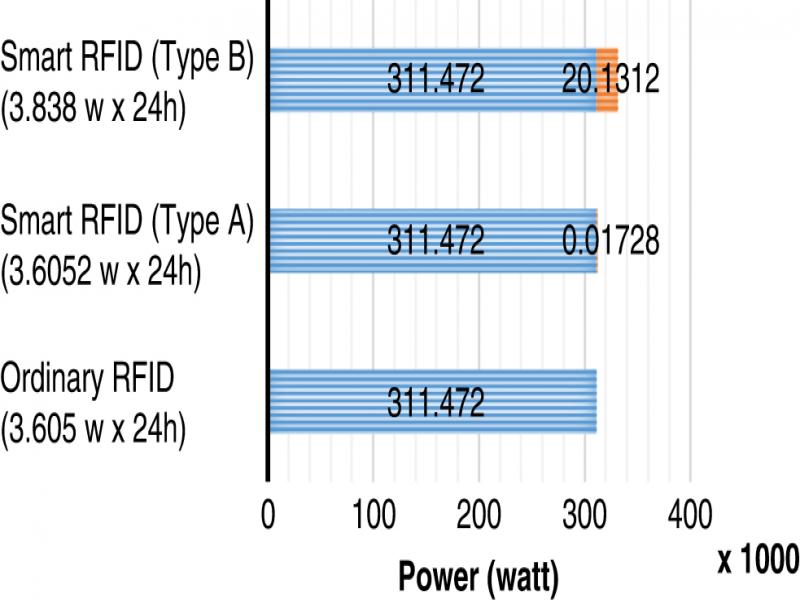
In this section, we reveal, evaluate and discuss the results of an empirical study reviewing the power efficiency of the ordinary RFID system compared to the smart RFID system, including both designs: Type A and Type B.
Figure 6 depicts the implementation of the smart RFID system, as illustrated in the diagram.
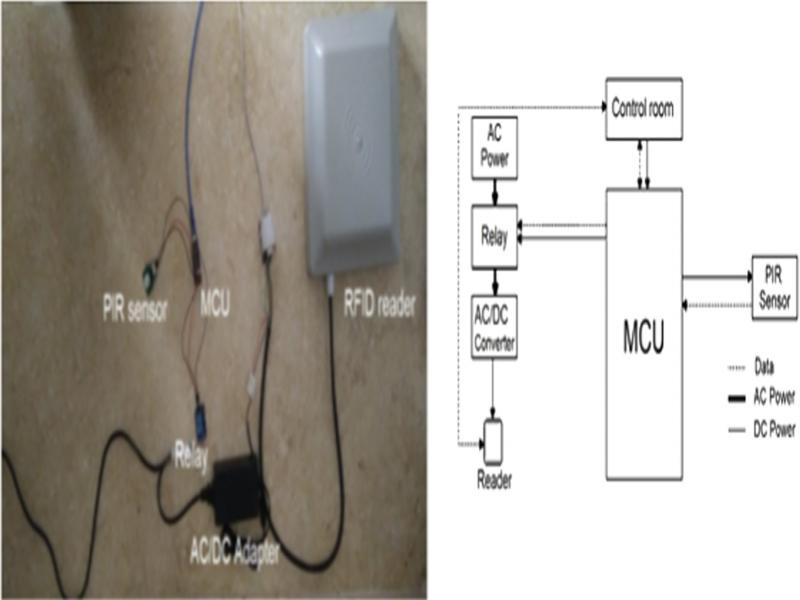
Figure 6:
Implementation of the optimal motion sensor-based smart RFID system.
Although it is possible to operate multiple readers with a single wide range (or well placed) motion sensor, we use, in this experiment, only one reader per sensor. Table 1 shows the power consumption of the smart RFID system compared to an ordinary RFID system, in both of the standby and the reading modes. The power consumption values were obtained from the datasheets of the components.
Table 1.
The power consumption of smart and ordinary RFID systems.
| Ordinary system | Smart RFID system (Type B) | Smart RFID system (Type A) | ||||
|---|---|---|---|---|---|---|
| Module | Standby mode | Reading mode | Standby mode | Reading mode | Standby mode | Reading mode |
| MCU | / | / | 232.5 mw | 232.5 mw | / | / |
| PIR sensor | / | / | 170 µw | 170 µw | 170 µw | 170 µw |
| AC/DC converter | 455 mw | 455 mw | 0 | 455 mw | 455 mw | 455 mw |
| RFID reader | 3.15 w | 3.15 w | 0 | 3.15 w | 0 w | 3.15 w |
| Total | 3.605 w | 3.605 w | 232.7 mw | 3.838 w | 455.2 mw | 3.6052 w |