
Table 1.
Sputtering parameters used for deposition of ZnO thin film.
| Target – substrate distance | 28 cm |
| Substrate temperature | 24 ± 2oC |
| RF power | 120 W |
| Ar-O2 ratio | 17.1–3.1 Sccm (85%–15%) |
| Ultimate pressure | 5 × 10⁻⁶ mbar |
| Working pressure | 1.4 × 10⁻² mbar |
| Deposition time | 15, 30, 45, and 60 min |
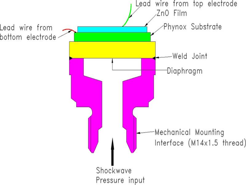
Figure 1:
Schematic of ZnO thin film-based sensor packaged for dynamic pressure sensing application.
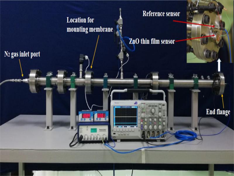
Figure 2:
Experimental test setup used for the characterization of dynamic pressure sensor.
Table 2.
Structural details of ZnO thin film derived from XRD.
| Sl. No. | Deposition duration (min) | 2θ (Deg) | FWHM (Deg) | Average grain size (nm) |
|---|---|---|---|---|
| 1 | 15 | 33.950 | 0.796 | 10.905 |
| 2 | 30 | 33.890 | 0.684 | 12.694 |
| 3 | 45 | 33.890 | 0.601 | 14.435 |
| 4 | 60 | 34.014 | 0.517 | 16.777 |
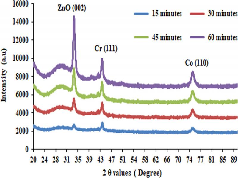
Figure 3:
XRD pattern of ZnO thin film deposited for different durations.
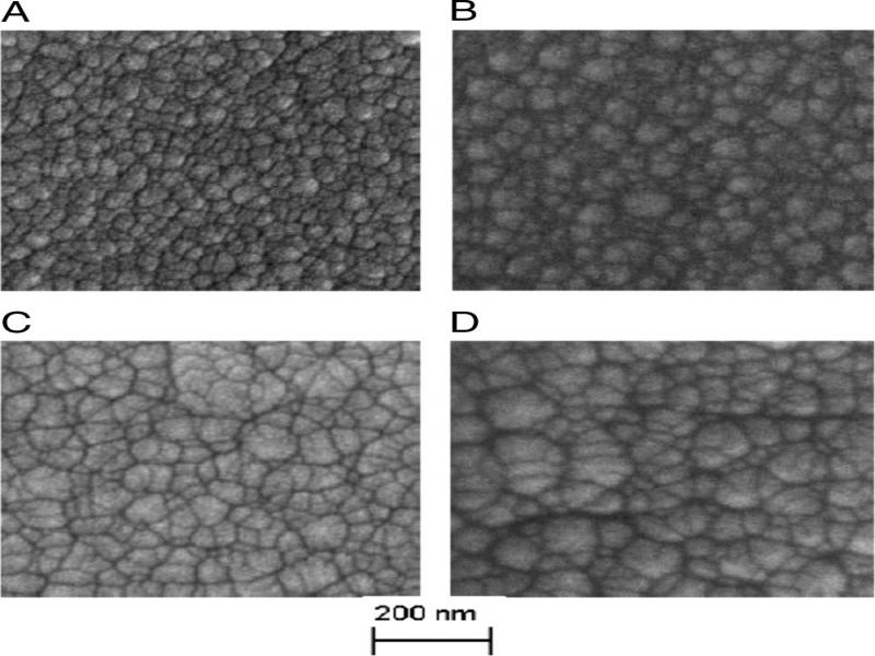
Figure 4:
FE-SEM image: surface morphology of the ZnO thin films for deposition durations of (A) 15 min, (B) 30 min, (C) 45 min, and (D) 60 min.
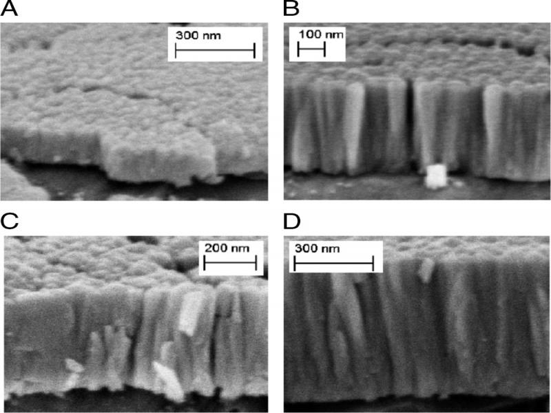
Figure 5:
FE-SEM image: cross-section of the ZnO thin films for deposition durations of (A) 15 min, (B) 30 min, (C) 45 min, and (D) 60 min.
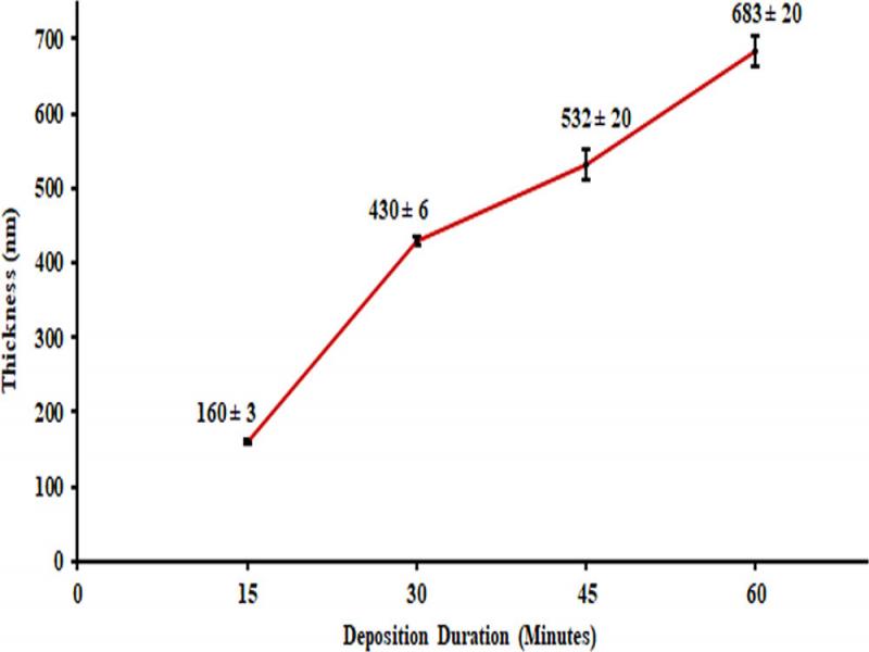
Figure 6:
Variation of film thickness with deposition duration.
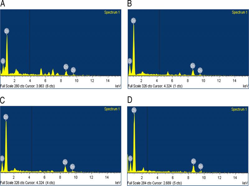
Figure 7:
EDS spectra of the thin films for the deposition durations of (A) 15 min, (B) 30 min, (C) 45 min, and (D) 60 min.
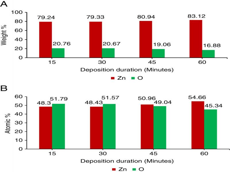
Figure 8:
(A) EDS result – composition of ZnO film in weight %, and (B) EDS result – composition of ZnO film in atomic %.
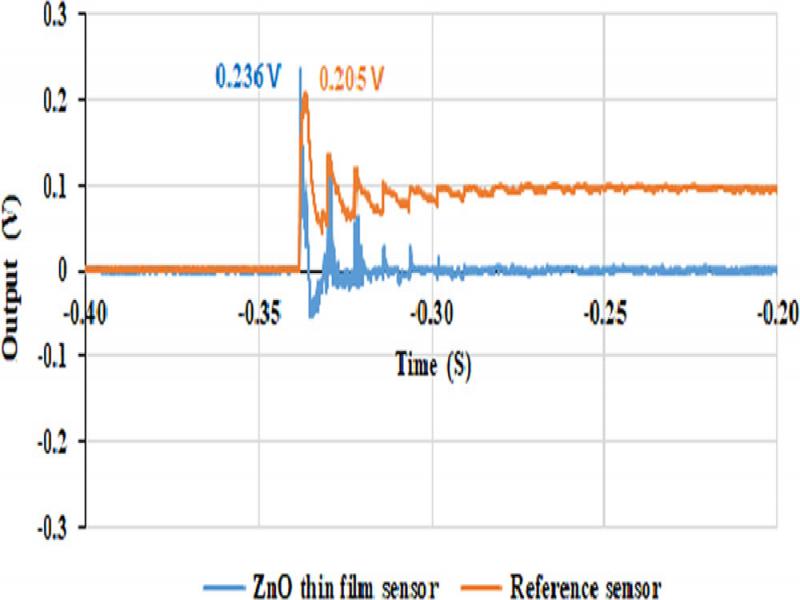
Figure 9:
Response of ZnO thin film sensor (Sensor 4) and reference sensor to shockwave (14.24 bar pressure).
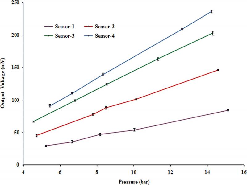
Figure 10:
Output of ZnO thin film sensors vs shockwave pressure.
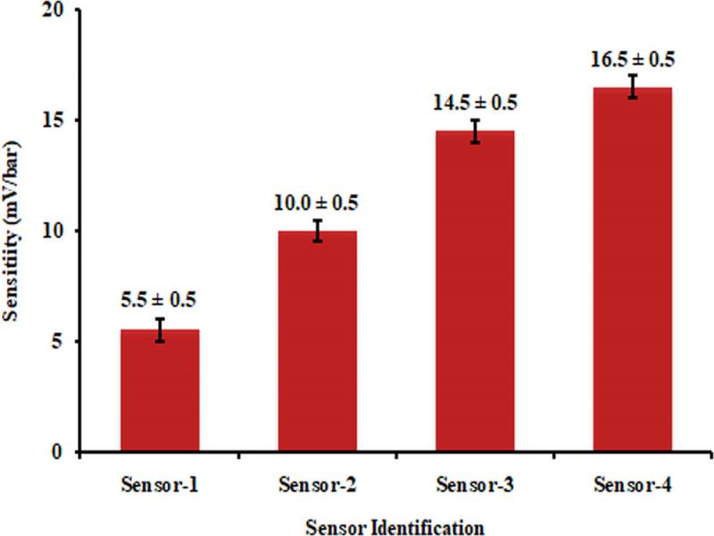
Figure 11:
Sensitivity of ZnO thin film dynamic pressure sensors.