
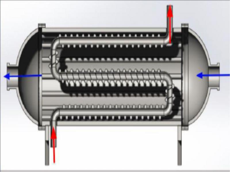
Figure 1.
Sectioned SolidWorks model of shell and tube heat exchanger with copper coil and finned inner wall.
TABLE I.
INTERNAL FLOW CALCULATIONS
| Temperature Inside Pipe | Length | Inner Diameter | Volume Flow Rate | Temperature of Pipe | Average Temperature Between the Surface of the Pipe and Liquid |
|---|---|---|---|---|---|
| Thi (C) | L (m) | Di (m) | Ts (C) | Tave (C) | |
| 75 | 1.397 | .013846 | .0000335 | 70 | 72.5 |
TABLE II.
EXTERNAL FLOW CALCULATIONS
| Temp. of Air | Outer Diameter of the Pipe | Temp. of Outer Pipe | Velocity of Air | Vertical Distance Between Pipes | Horizontal Distance Between Pipes | Length the Air Travels | Average Temp. Between the Surface of the Pipe and Liquid |
|---|---|---|---|---|---|---|---|
| Tci (C) | Do (m) | Tso (C) | St (m) | Sl (m) | Lo (m) | Taveo (C) | |
| 20 | .015875 | 45 | .222 | .057785 | 0.127 | 1.9304 | 32.5 |
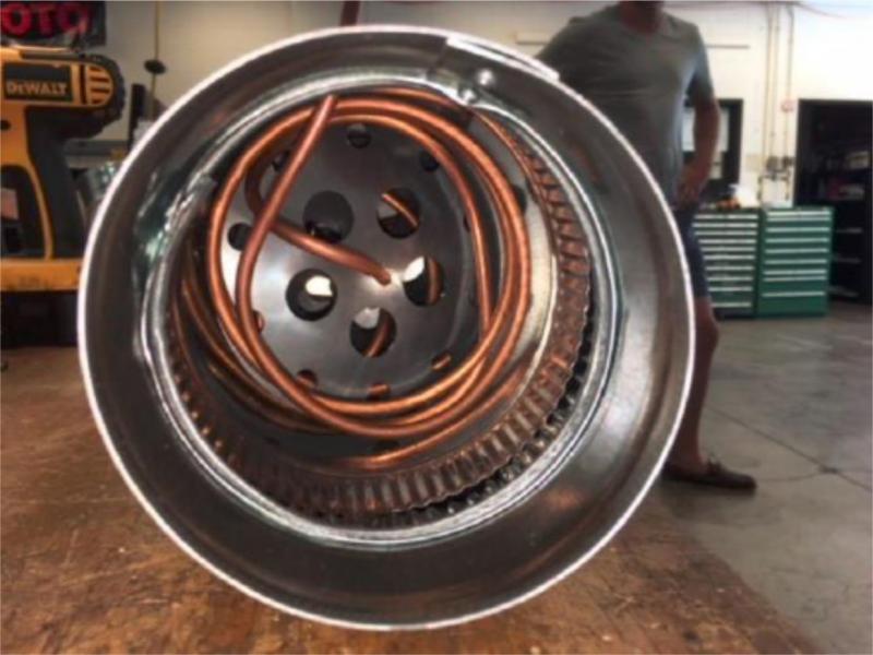
Figure 2.
The heat exchanger prototype
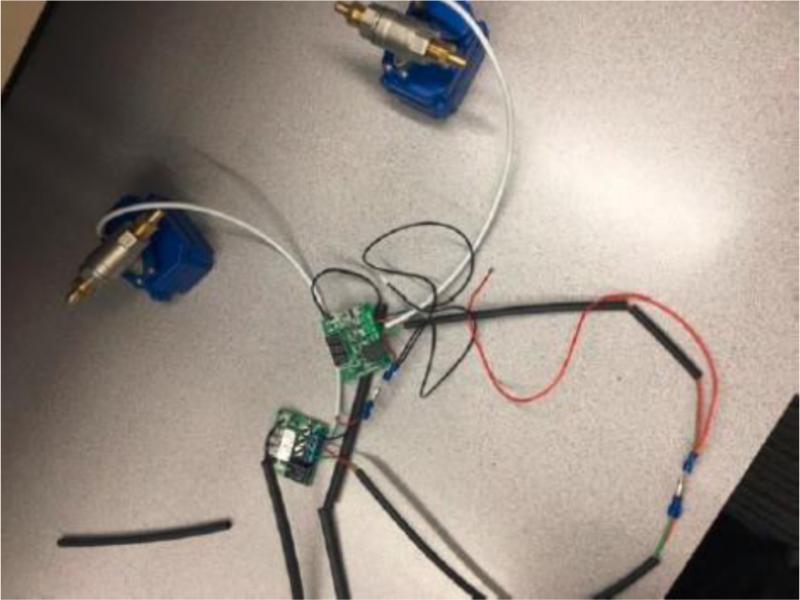
Figure 3.
The electronic part of the heat exchanger
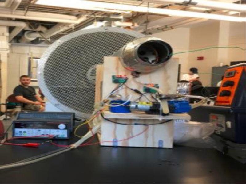
Figure 4.
Testing the heat exchanger
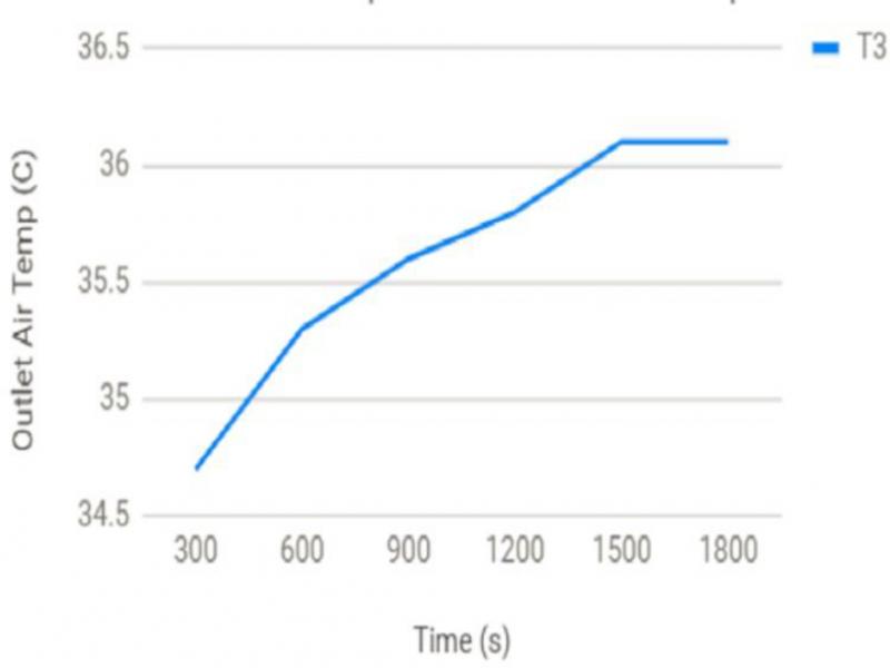
Figure 5.
Time vs. outlet air temperature at 20% wind speed
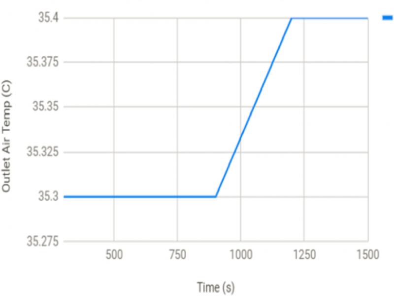
Figure 6.
Time vs. outlet air temperature at 40% wind speed
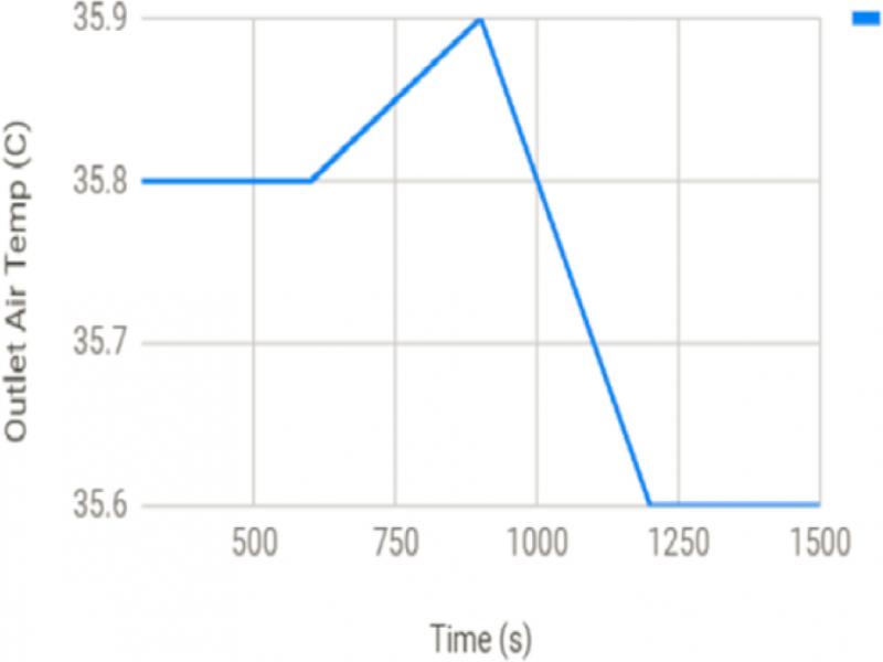
Figure 7.
Time vs. outlet air temperature at 60% wind speed
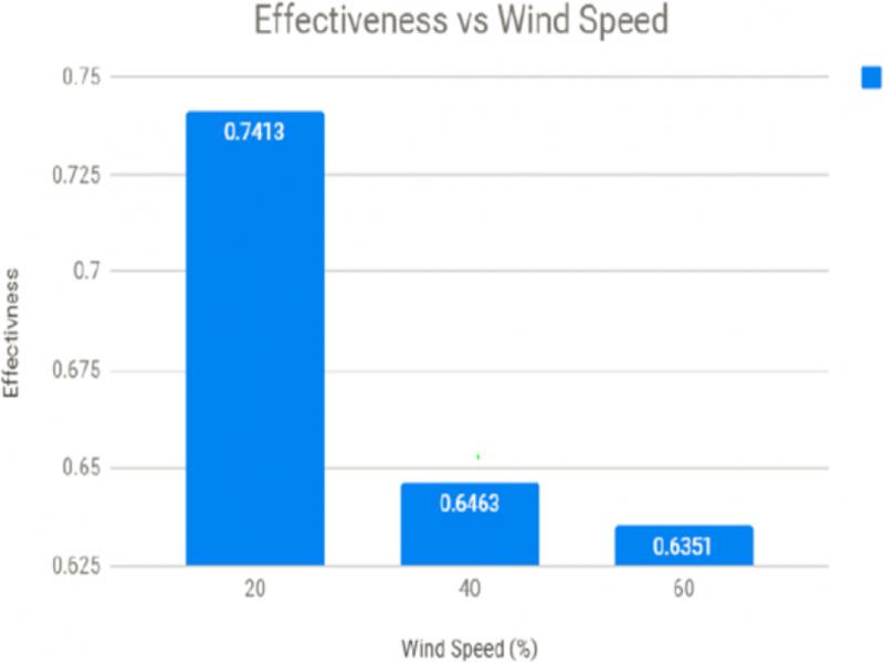
Figure 8.
Effectiveness vs wind speed