
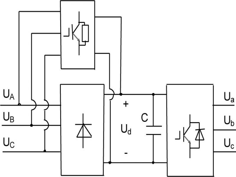
Figure 1.
Topology of converter without electrolytic capacitor
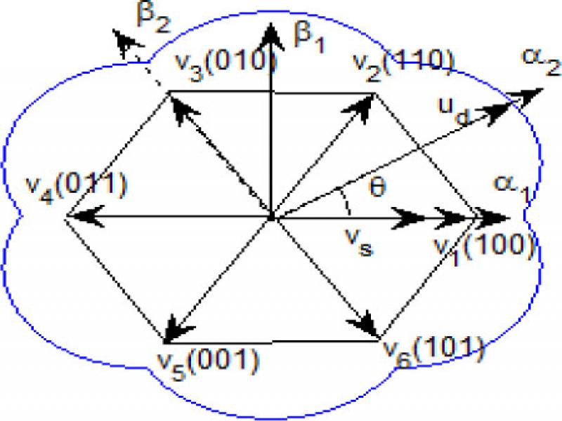
Figure 2.
Dc-link voltage and space voltage vector
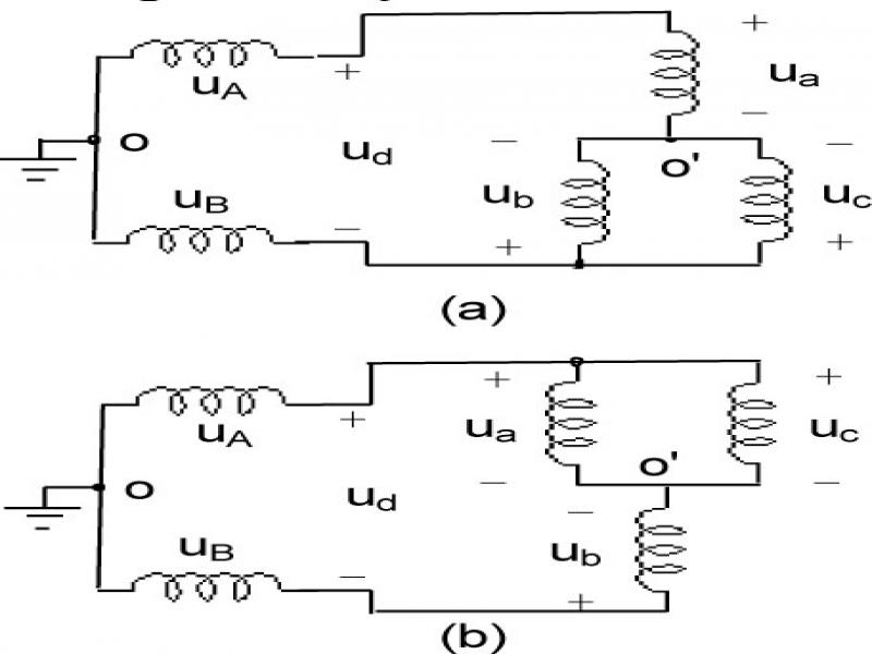
Figure 3.
Inverter equivalent circuit
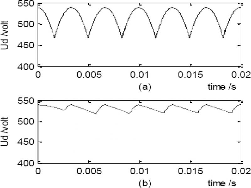
Figure 4.
Contrast of dc-link voltage of two converters with resistance-inductance load
Table I.
PERFORMANCE CONTRAST OF TWO CONVERTER WITH SAME LOAD OF RESISTANCE AND INDUCTANCE
| Item | Frequency | New converter | Traditional converter |
|---|---|---|---|
| THD | 5 Hz | 31.1 | 30.8 |
| 15Hz | 11.1 | 11.2 | |
| 25 Hz | 8.1 | 6.9 | |
| 50 Hz | 0.8 | 4.0 | |
| Uab(V) | 5 Hz | 40.1 | 42 |
| 15Hz | 115 | 119.2 | |
| 25 Hz | 189.8 | 196.8 | |
| 50 Hz | 380.9 | 366.5 | |
| η | 50 Hz | 1.0 | 0.96 |
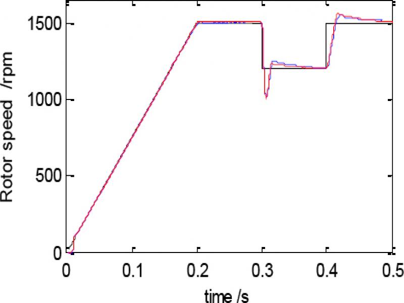
Figure 5.
Contrast of speeds of a motor fed by two converters with vector control
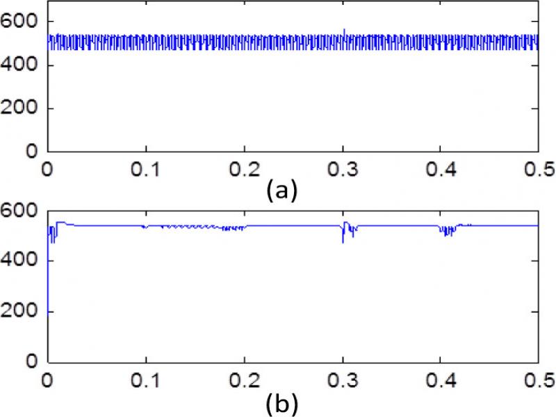
Figure 6.
The dc link voltages of two converters with a motor load. (a) the novel. (b) the traditonal
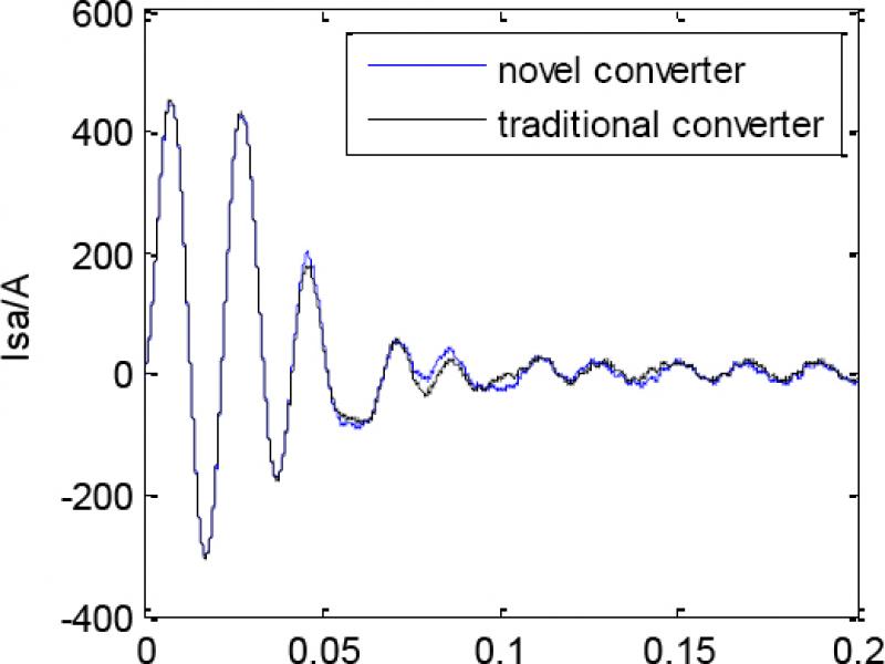
Figure 7.
Stator current response of induction motor starting process
Table II.
Performance contrast of two converters with a MOTOR LOAD
| Item | frequency | New converter | Traditional converter |
|---|---|---|---|
| THD (%) | 5 Hz | 19.4 | 14.6 |
| 15Hz | 11.2 | 6.97 | |
| 25 Hz | 6.73 | 6.2 | |
| 50 Hz | 37.7 | 3.5 | |
| Uab(V) | 5 Hz | 41.5 | 40.3 |
| 15Hz | 118.1 | 117.1 | |
| 25 Hz | 194.1 | 189.4 | |
| 50 Hz | 386.8 | 385.4 | |
| η | 50 Hz | 1.02 | 1.01 |
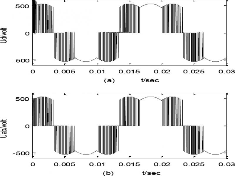
Figure 8.
Output voltage of two models of converter. (a) The mathematical model. (b) the novel converter