
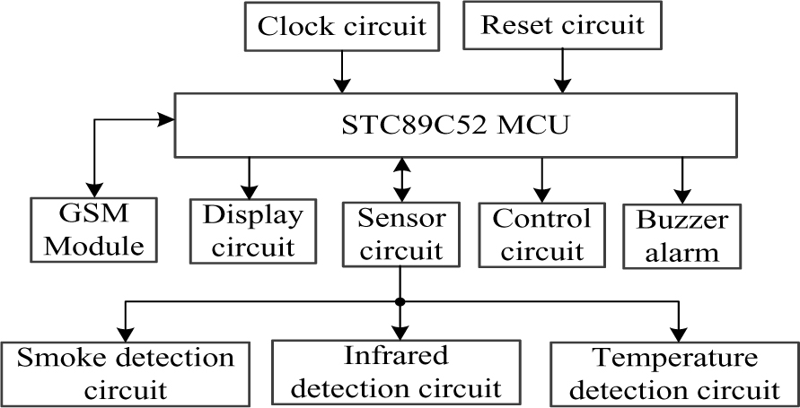
Figure 1.
System block diagram.
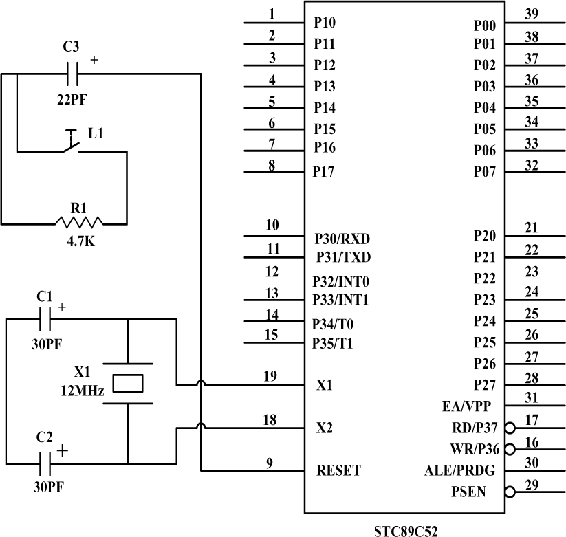
Figure 2.
Minimum system of the single chip.
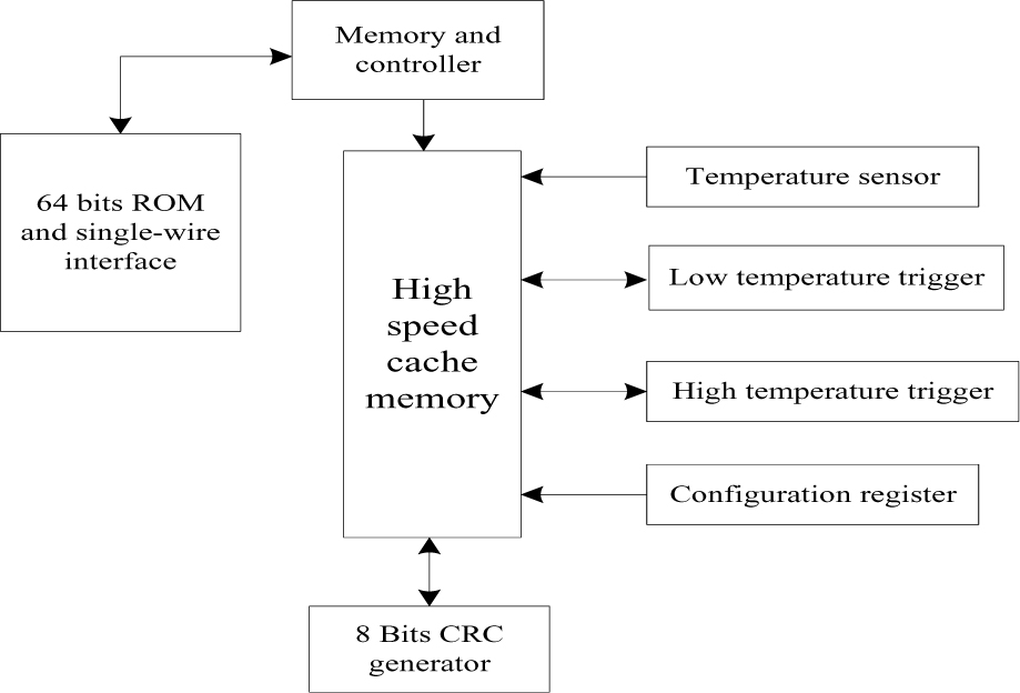
Figure 3.
The internal block of DS18B20.
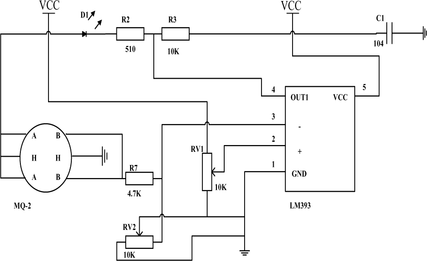
Figure 4.
The circuit of the smoke and the combustible gas.
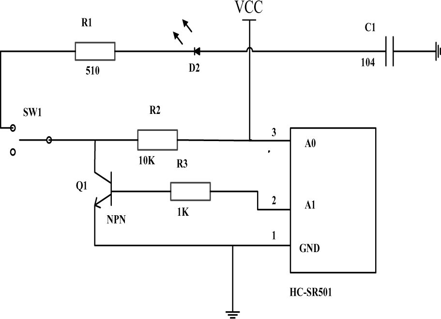
Figure 5.
The infrared detection circuit.
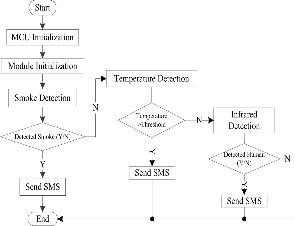
Figure 6.
Main program of the systemm.
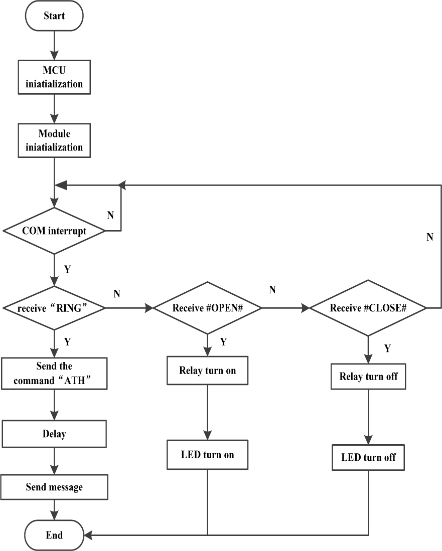
Figure 7.
TC35 module program flow chart.
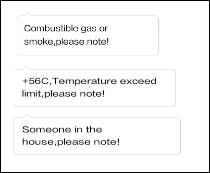
Figure 8.
GSM sending SMS.

Figure 9.
GSM receiving SMS