
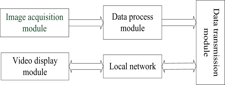
Figure 1.
Overall structure diagram of the system
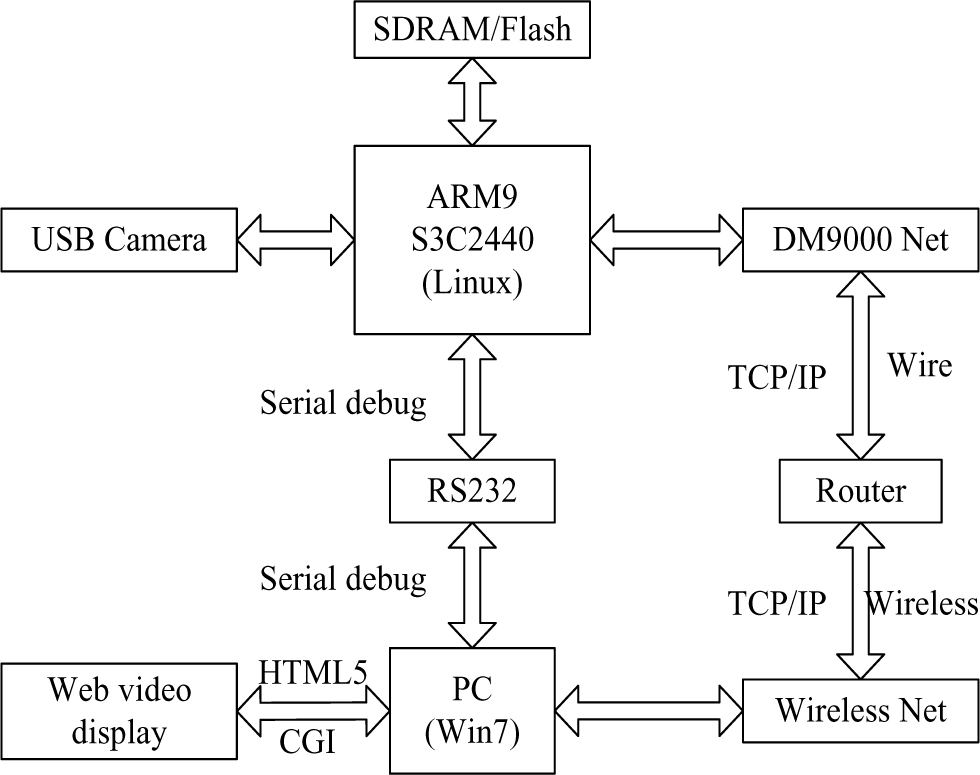
Figure 2.
The system hardware structure
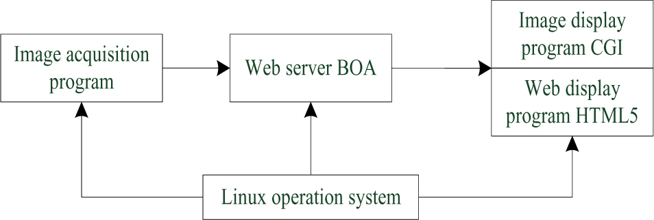
Figure 3.
The system software structure
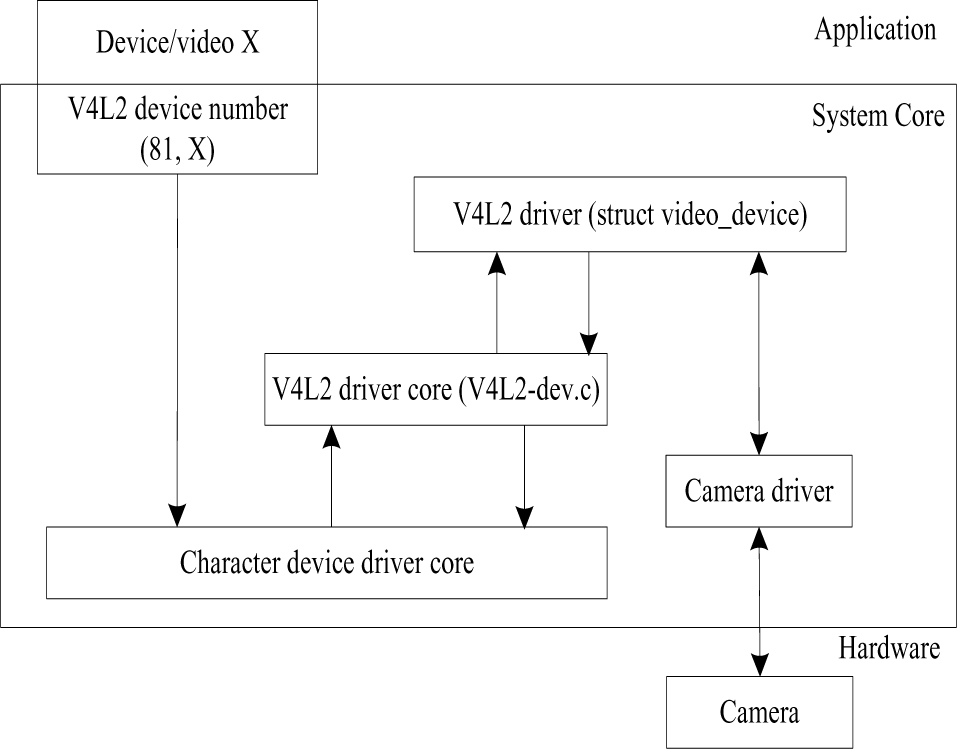
Figure 4.
The structure of V4L2
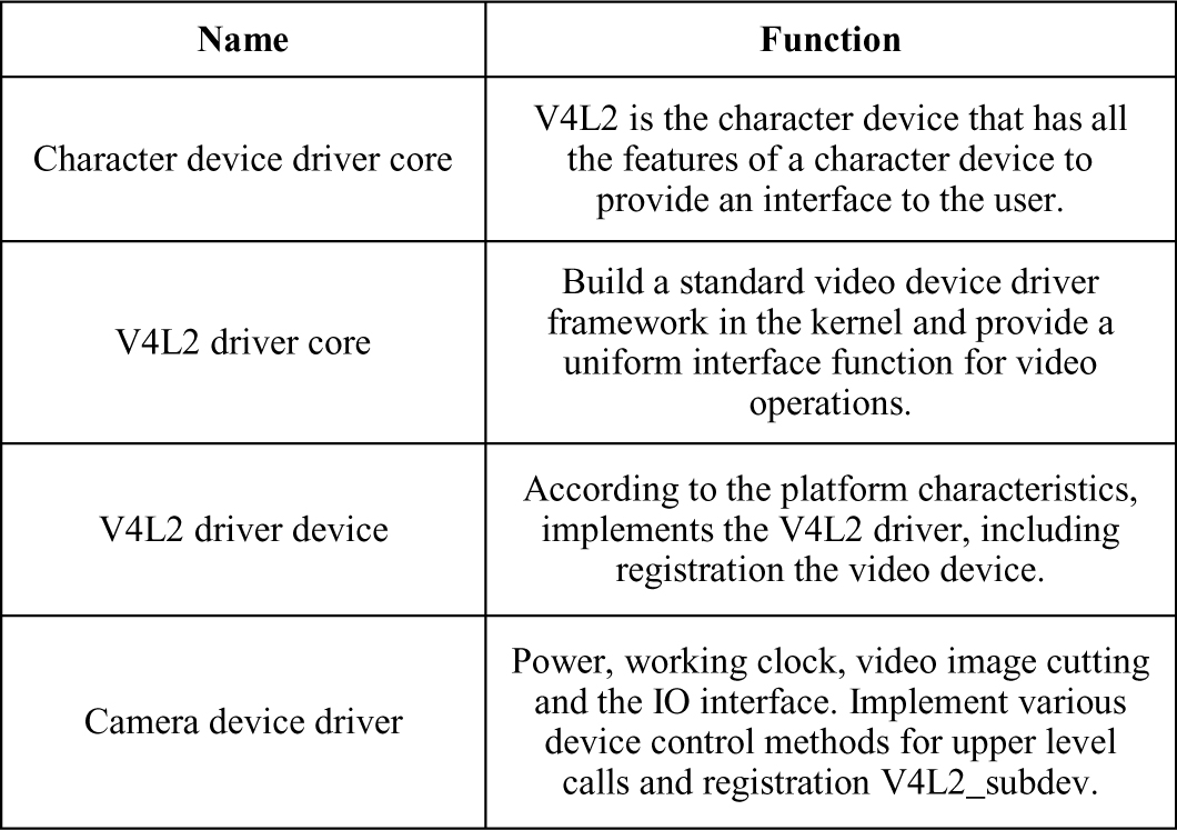
TABLE 1.
THE FRAME STRUCTURE OF V4L2
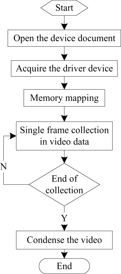
Figure 5.
The image collection flow chart
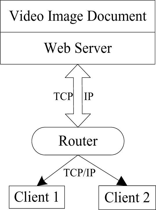
Figure 6.
The net transmission based on the TCP/IP protocol
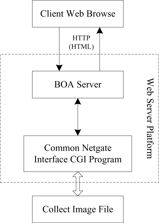
Figure 7.
The flow chart of the CGI
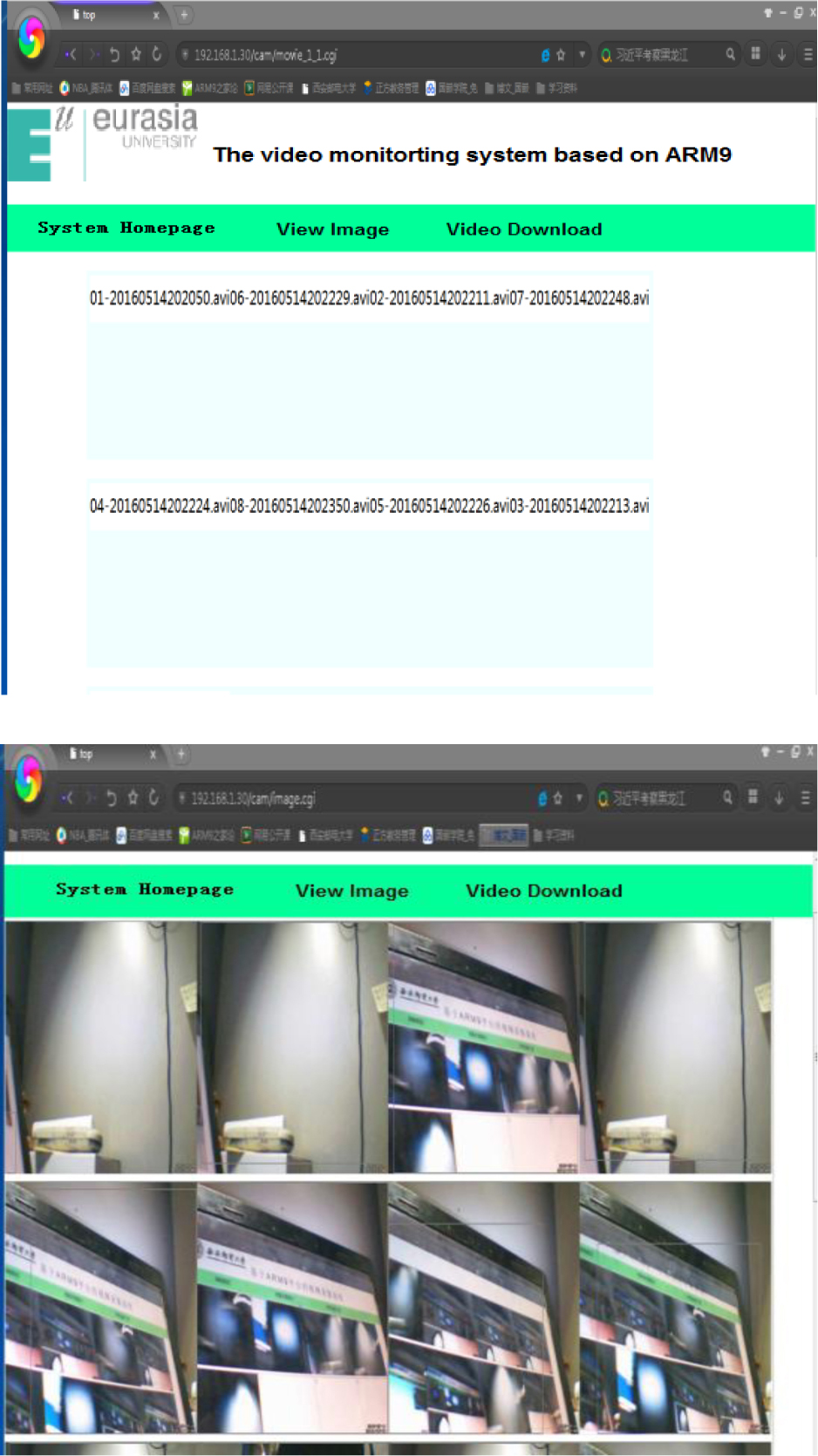
Figure 8.
The test result of the proposed monitoring system