
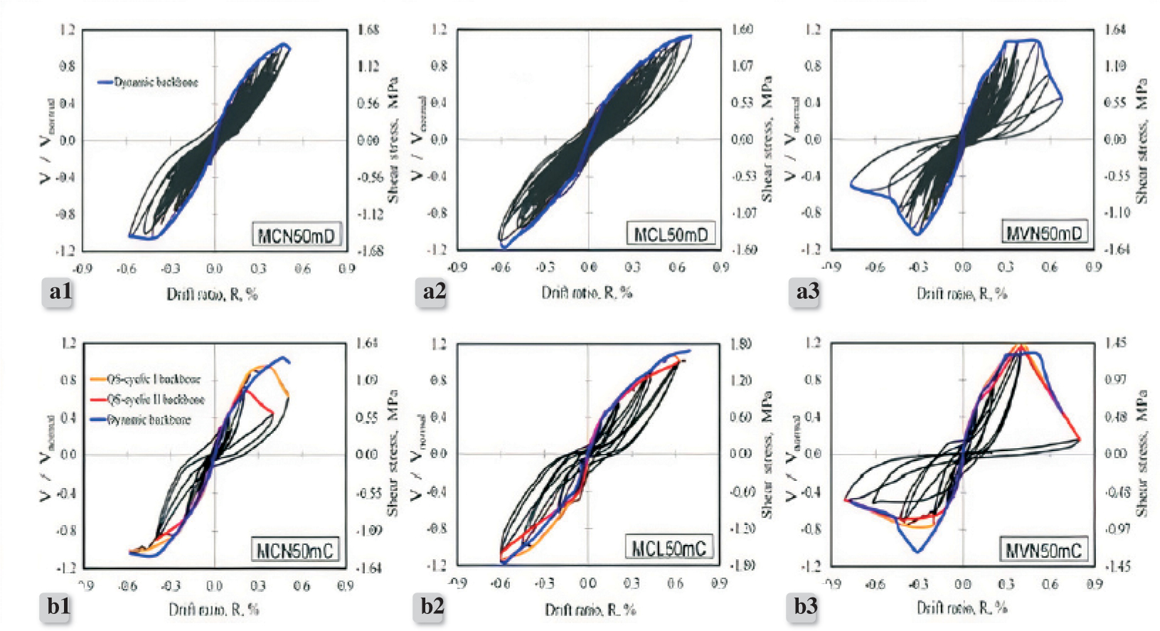
Figure 1.
Hysteresis curves of walls that failed diagonal tension a) shaking table tests b) QS-cyclic tests [22]
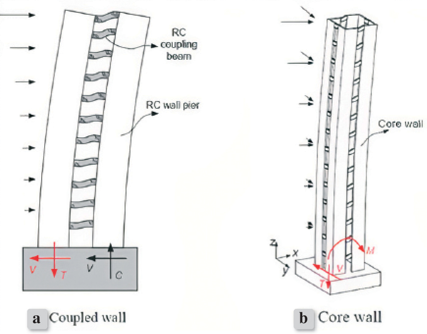
Figure 2.
The tensile stress at the coupled and core wall systems [27]
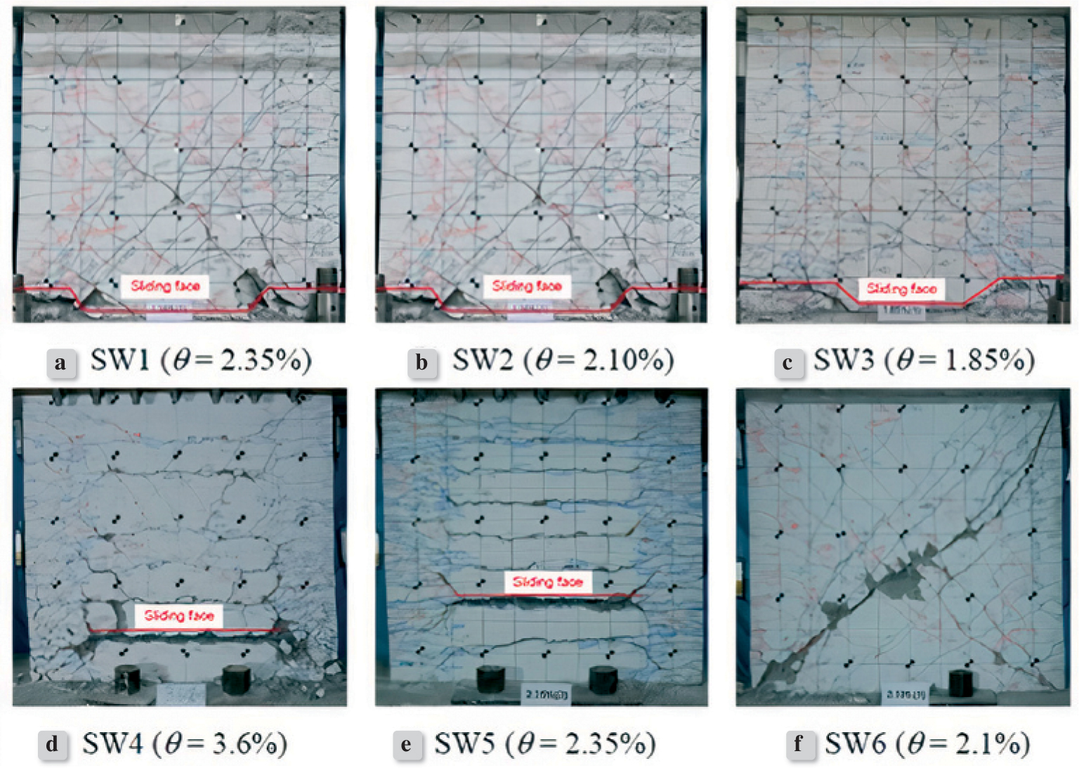
Figure 3.
Pictures of tested shear walls [27]
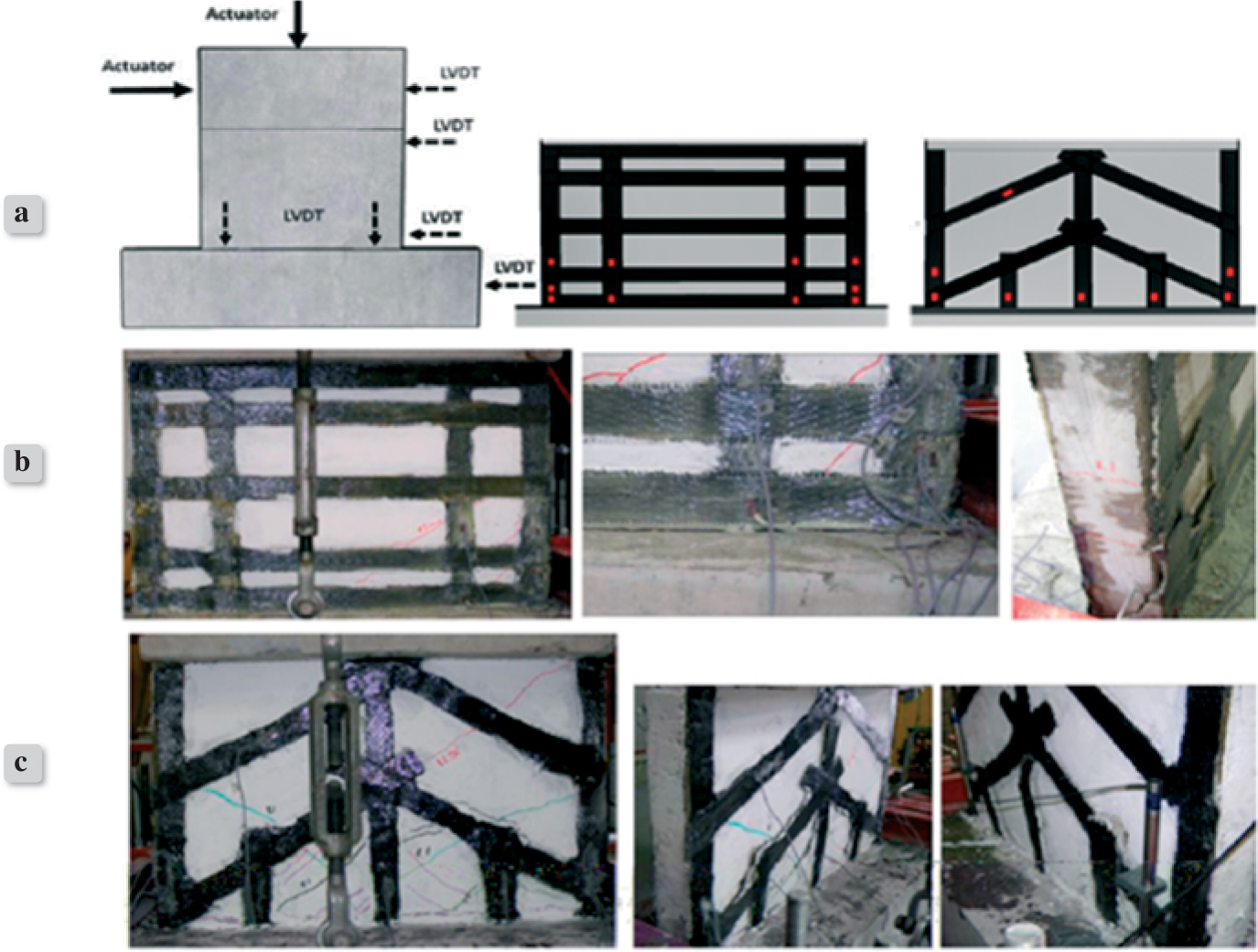
Figure 4.
a) Schematic detail of strengthened shear walls b) Failure pattern of strengthened strip shape shear wall c) Failure pattern of strengthened diagonal shape shear wall
Table 1.
The dimensions and reinforcement characteristics of tested shear walls [38]
| Concrete Type | No | Wall | tw (mm) | lw (mm) | hw/lw | Web reinforcement | Boundary element | ||||
|---|---|---|---|---|---|---|---|---|---|---|---|
| Layout | ρh,v (%) | Longitudinal | Stirrup(s) | ||||||||
| Lay | ρ(%) | Lay | ρ(%) | ||||||||
| 1L | MCL50M | 102 | 2397 | 1.01 | 3Ø500 mm | 0.14 | 8 ≠ 5 | 0.68 | 2Ø150 mm | 0.42 | |
| 2L | MCL100M | 101 | 2398 | 1.01 | 3Ø250 mm | 0.28 | 8 ≠ 6 | 0.98 | 0.42 | ||
| 3L | MCL50C | 101 | 2398 | 1.01 | 3Ø500 mm | 0.14 | 8 ≠ 5 | 0.68 | 0.42 | ||
| 4L | MCL100C | 101 | 2399 | 1.01 | 3Ø250 mm | 0.28 | 8 ≠ 6 | 0.98 | 0.42 | ||
| Lightweight concrete | 5L | MRL100C | 101 | 5413 | 0.45 | 3Ø250 mm | 0.28 | 6 ≠ 6 | 0.32 | 0.42 | |
| 6L | MRL50mC | 106 | 5415 | 0.44 | mesh 6x6-6/6 | 0.12 | 8 ≠ 5 | 0.21 | 0.40 | ||
| 7L | MLC50mC | 100 | 2403 | 1.00 | mesh 6x6-6/6 | 0.12 | 6 ≠ 6 | 0.74 | 0.43 | ||
| 8L | MEL50mC | 100 | 1221 | 1.94 | mesh 6x6-6/6 | 0.12 | 4 ≠ 6 | 0.99 | 0.43 | ||
| 9L | MCL50mD | 82 | 1917 | 1.00 | mesh 6x6-8/8 | 0.11 | 6 ≠ 5 | 0.79 | 2Ø180 mm | 0.44 | |
| 10L | MCL50D | 82 | 1912 | 1.00 | 3Ø320 mm | 0.27 | 8 ≠ 5 | 1.06 | 0.44 | ||
| 1N | MCN50M | 102 | 2402 | 1.01 | 3Ø500 mm | 0.14 | 8 ≠ 5 | 0.67 | 2Ø150 mm | 0.42 | |
| 2N | MCN100M | 101 | 2402 | 1.01 | 3Ø250 mm | 0.28 | 8 ≠ 6 | 0.98 | 0.42 | ||
| 3N | MCN50C | 102 | 2399 | 1.01 | 3Ø500 mm | 0.14 | 8 ≠ 5 | 0.68 | 0.42 | ||
| 4N | MCN100C | 101 | 2397 | 1.01 | 3Ø250 mm | 0.28 | 8 ≠ 6 | 0.98 | 0.42 | ||
| Normal weight concrete | 5N | MRN100C | 100 | 5400 | 0.45 | 3Ø250 mm | 0.28 | 4 ≠ 6 | 0.22 | 0.43 | |
| 6N | MRN50mC | 103 | 5396 | 0.45 | mesh 6x6-6/6 | 0.12 | 8 ≠ 5 | 0.22 | 0.41 | ||
| 7N | MCN50mC | 103 | 2398 | 1.01 | mesh 6x6-6/6 | 0.12 | 6 ≠ 6 | 0.72 | 0.42 | ||
| 8N | MEN50mC | 101 | 1239 | 1.99 | mesh 6x6-6/6 | 0.12 | 4 ≠ 6 | 0.96 | 0.42 | ||
| 9N | MCN50mD | 83 | 1916 | 1.00 | mesh 6x6-8/8 | 0.11 | 6 ≠ 5 | 0.78 | 2Ø180 mm | 0.43 | |
| 10N | MCN50D | 84 | 1921 | 1.00 | 3Ø320 mm | 0.26 | 8 ≠ 5 | 1.02 | 0.42 | ||
Table 2.
Axial load ratio of analyzed shear walls [40]
| Shear wall | Axial load ratio | Axial load (kN) |
|---|---|---|
| SW1 | 0.1 | 497 |
| SW2 | 0.2 | 994 |
| SW3 | 0.3 | 1491 |
| SW4 | 0.4 | 1988 |
| SW5 | 0.5 | 2485 |
| SW6 | 0.6 | 2982 |
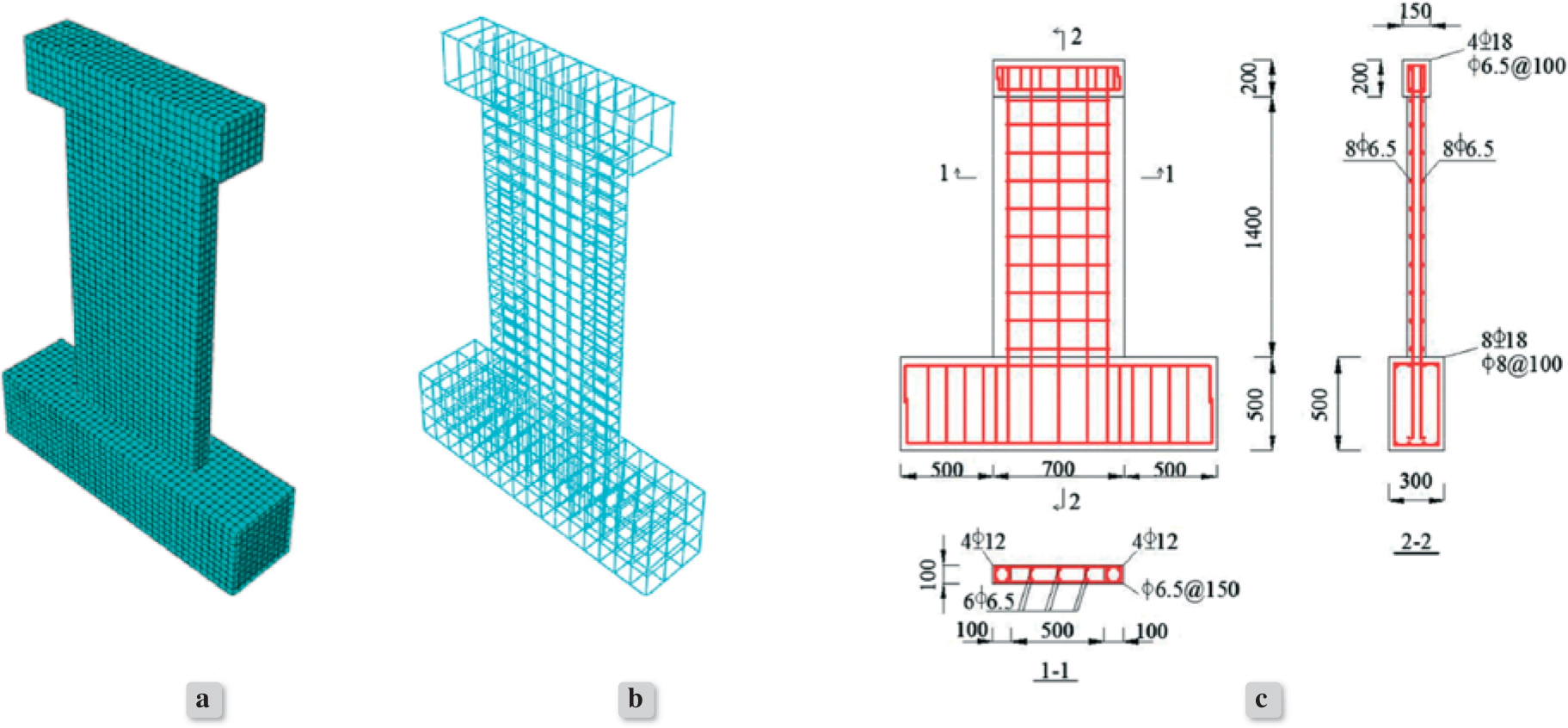
Figure 5.
The finite element model a) shear wall b) reinforcement bars c) geometries and reinforcement details of analyzed shear wall [40]
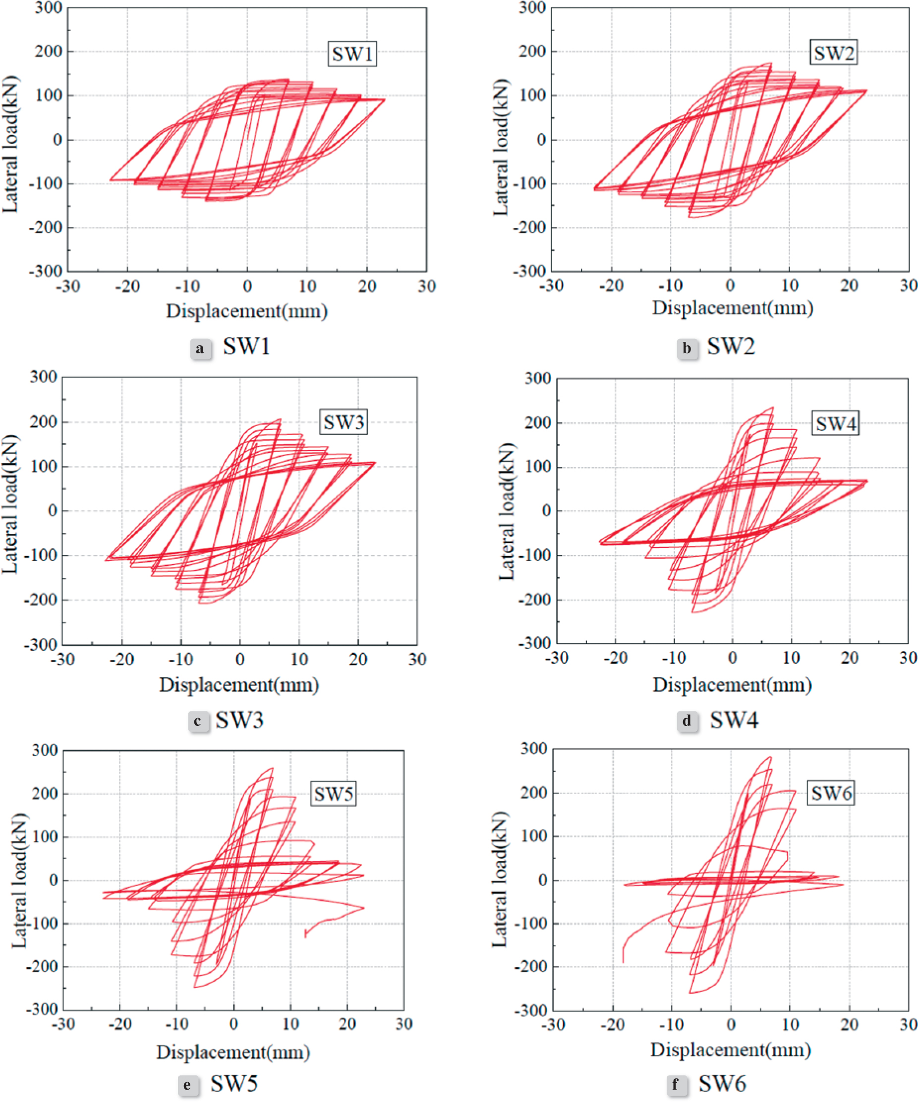
Figure 6.
Load-displacement hysteresis curves of the shear walls [40]
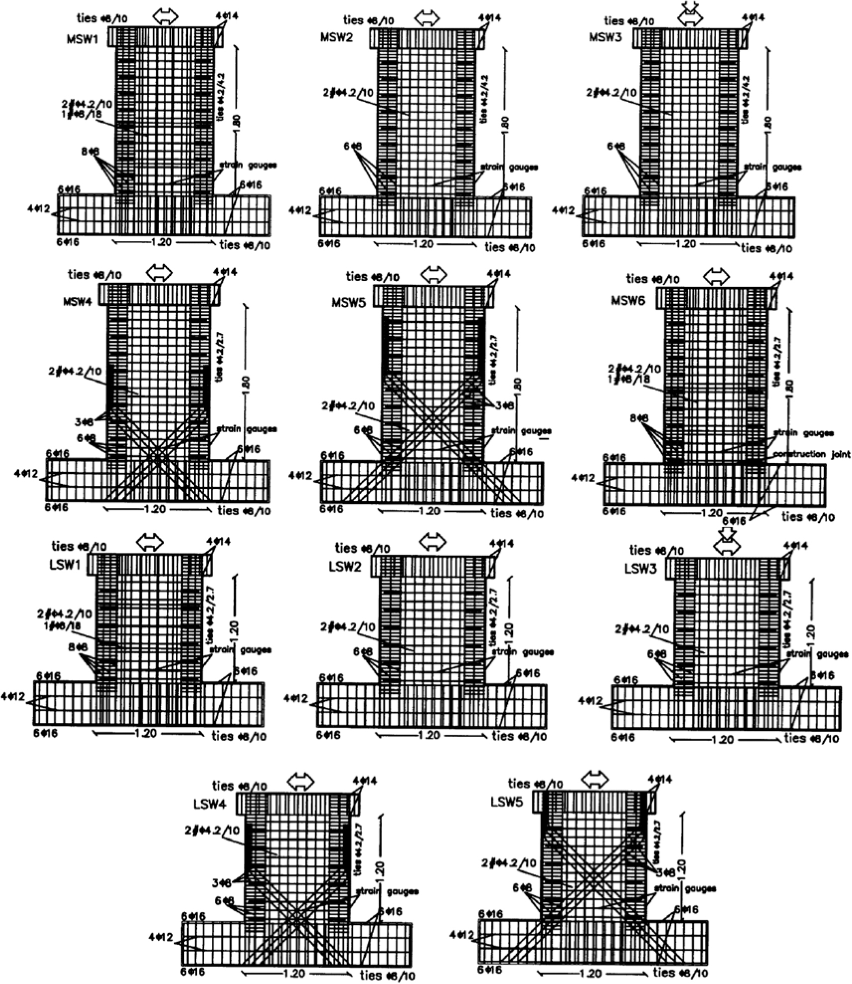
Figure 7.
Reinforcement layouts of shear walls [43]
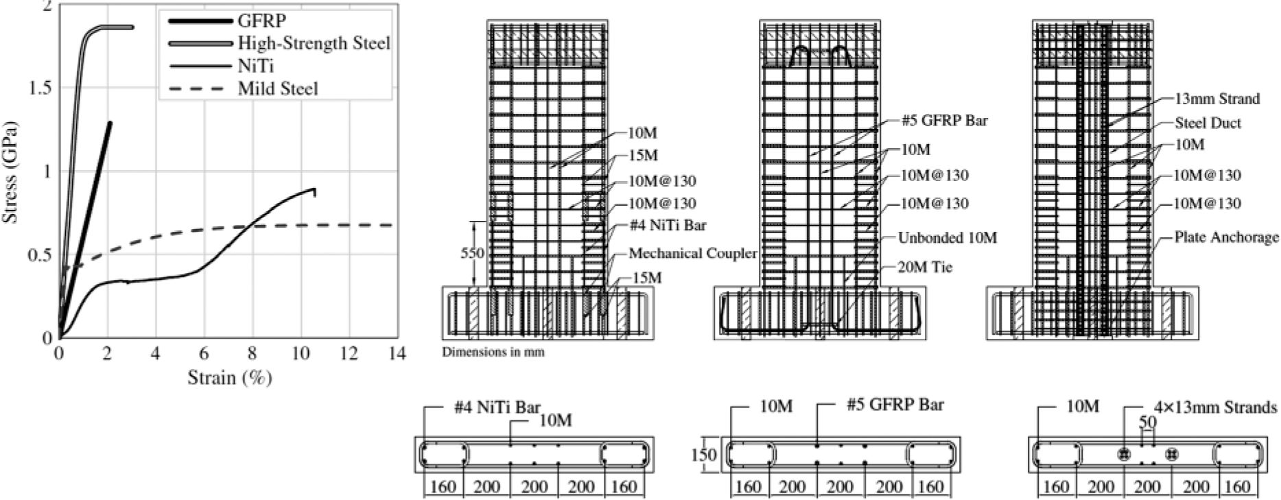
Figure 8.
Tensile stress-strain relationship of the reinforcements and reinforcement details of the shear walls [44]
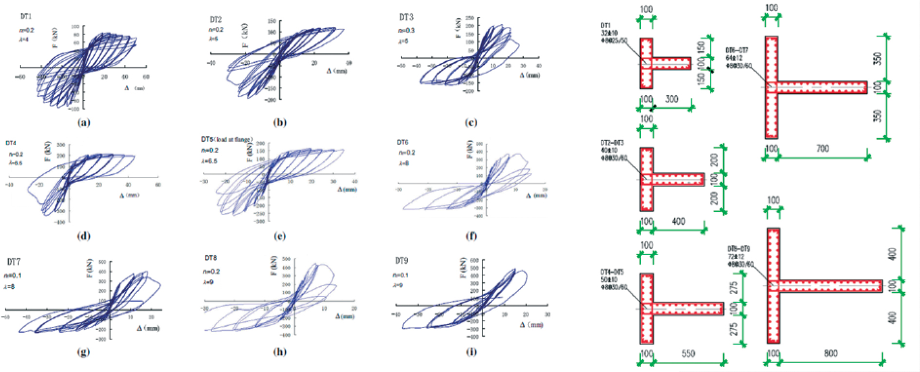
Figure 9.
Reinforcement details and hysteric loops of the specimens [7]
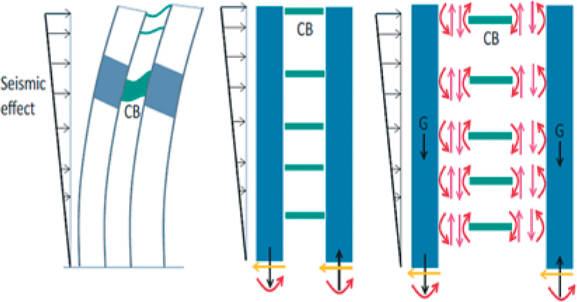
Figure 10.
Coupled shear wall systems [56]
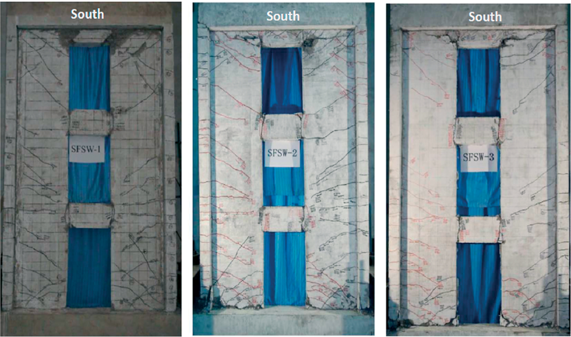
Figure 11.
Crack patterns of CSWs [56]
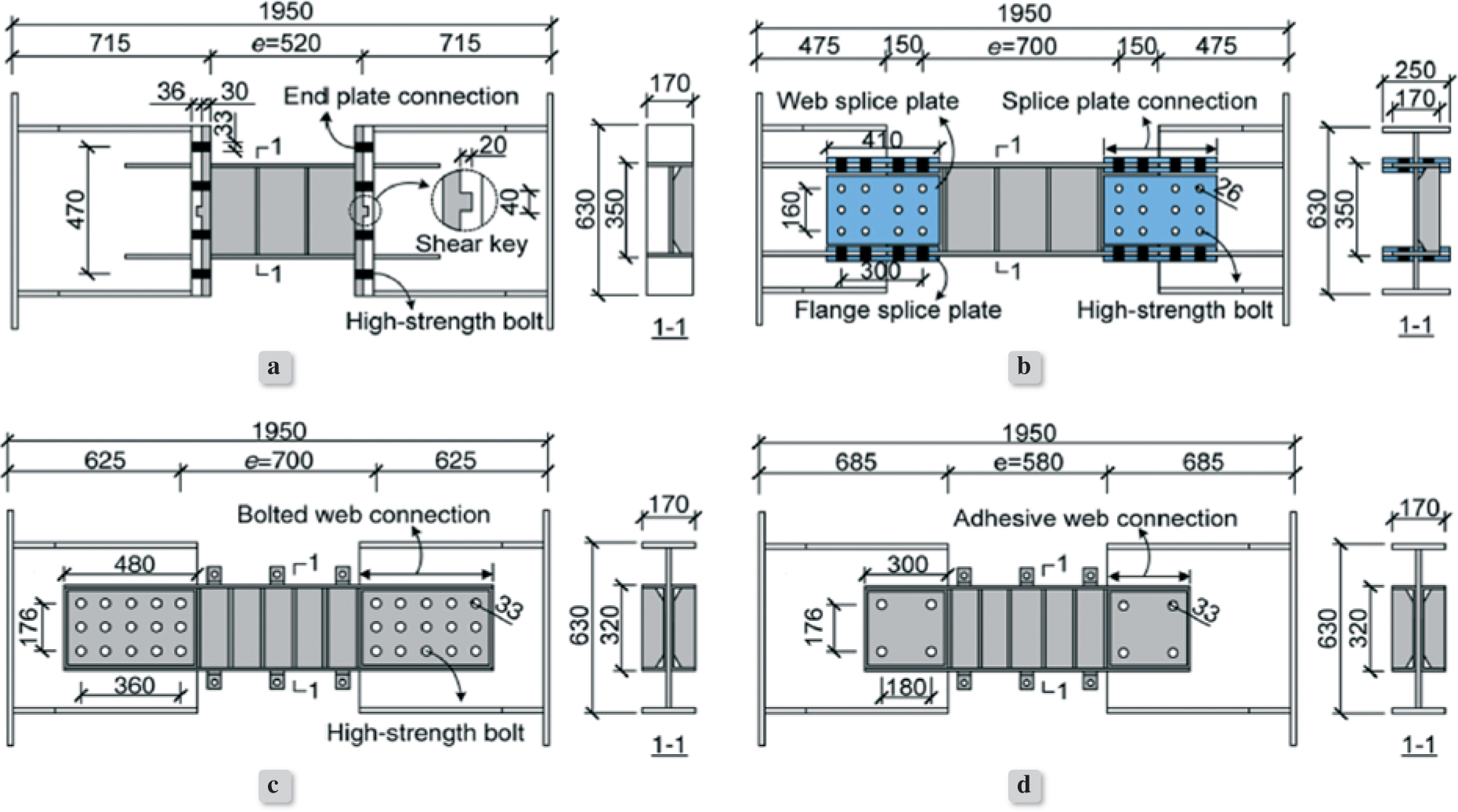
Figure 12.
Geometry and dimensions of tested specimens [60]
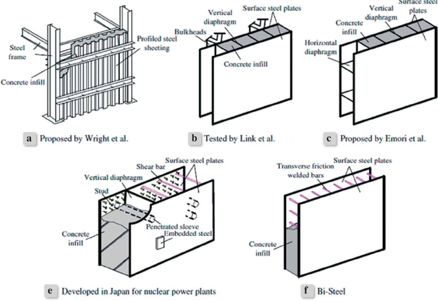
Figure 13.
Different types of CFDSP shear walls [69]
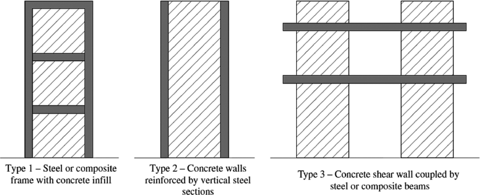
Figure 14.
Composite structural systems [68]
Table 3.
Shear wall parameters of tested specimens [69]
| Specimen | Cross section (mm x mm) | Shear span ratio | Cubic compressive strength of concrete | Mesh reinforcement | Steel plate thickness of boundary column (mm) | Steel plate thickness of wall body (mm) | Steel content ratio (%) | Axial compressive force (kN) |
|---|---|---|---|---|---|---|---|---|
| CFSCW-1 | 1284x214 | 2.0 | 87.5 | 0 | 5 | 5 | 7.1 | 7375 |
| CFSCW-2 | 1284x214 | 2.0 | 86.1 | 0 | 5 | 5 | 7.1 | 7319 |
| CFSCW-3 | 1284x214 | 2.0 | 86.1 | 0 | 5 | 5 | 7.1 | 7319 |
| CFSCW-4 | 1284x214 | 2.0 | 89.8 | 0 | 4 | 4 | 5.8 | 7535 |
| CFSCW-5 | 1284x214 | 2.0 | 88..1 | 0 | 3 | 3 | 4.6 | 7404 |
| CFSCW-6 | 1284x214 | 2.0 | 65.0 | 0 | 5 | 5 | 7.1 | 5863 |
| CFSCW-7 | 1284x214 | 2.0 | 102.6 | 0 | 5 | 5 | 7.1 | 7900 |
| CFSCW-8 | 1284x214 | 2.0 | 88.4 | 0 | 6 | 4 | 7.1 | 7807 |
| CFSCW-9 | 1284x214 | 2.0 | 83.3 | Ø8@130 | 5 | 5 | 7.1 | 7375 |
| CFSCW-10 | 750x125 | 2.0 | 83.7 | 0 | 3 | 3 | 7.1 | 2756 |
| CFSCW-11 | 750x125 | 1.5 | 80.7 | 0 | 3 | 3 | 7.1 | 2718 |
| CFSCW-12 | 750x125 | 1.0 | 88.0 | 0 | 3 | 3 | 7.1 | 2816 |
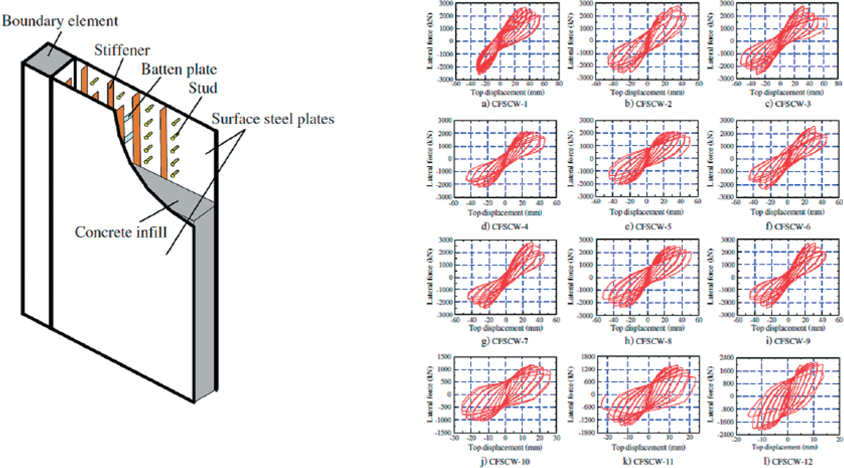
Figure 15.
Shear wall parameters and the results of hysteric curves of tested specimens [69]
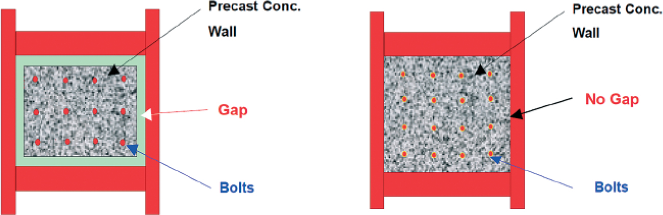
Figure 16.
Traditional and innovative shear walls [74]
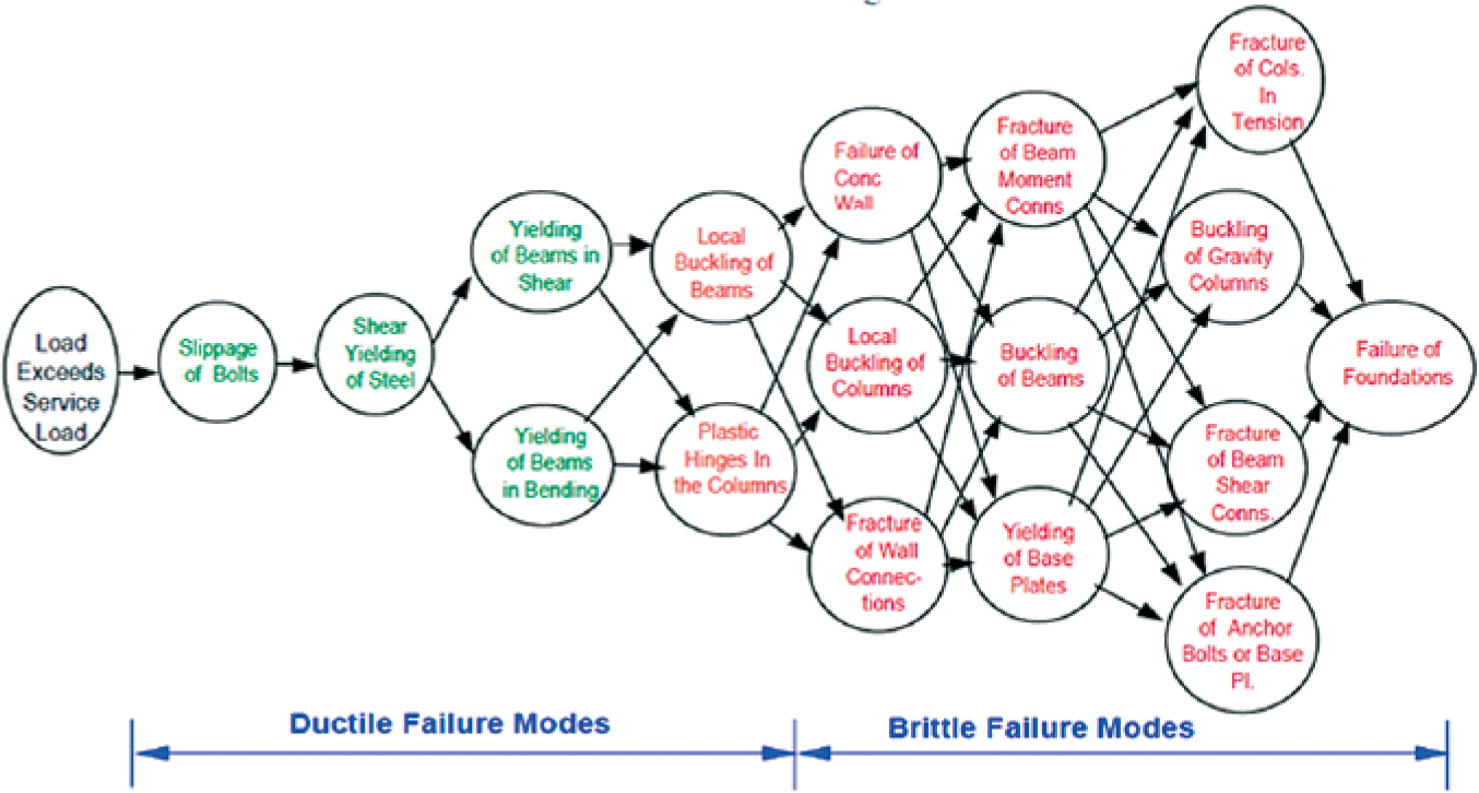
Figure 17.
Hierarchical order of failure modes of composite shear walls [74]
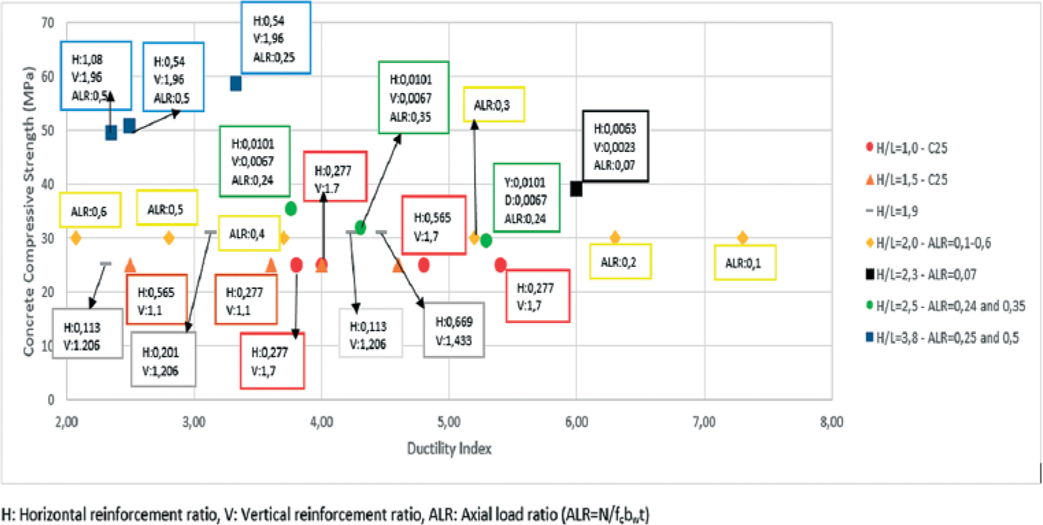
Figure 18.
Concrete compressive strength – ductility index
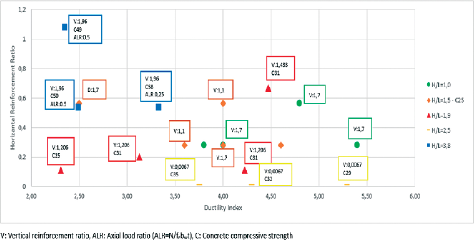
Figure 19.
Horizontal reinforcement ratio – ductility index
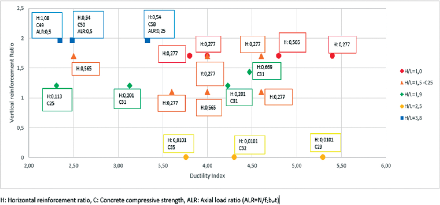
Figure 20.
Vertical reinforcement ratio – ductility index
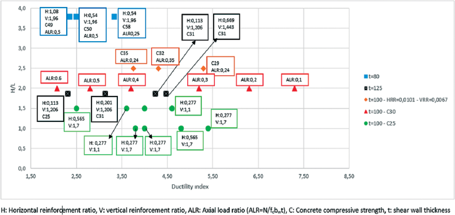
Figure 21.
H/L – ductility index
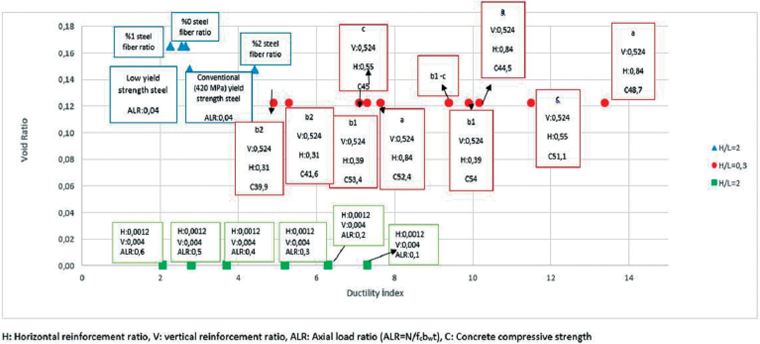
Figure 22.
Void Ratio – Ductility index for varying reinforcement details
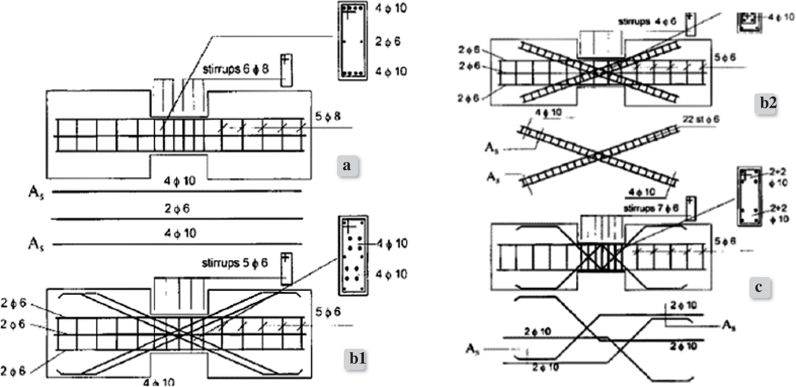
Figure 23.
Reinforcement details for shear walls with openings [57]
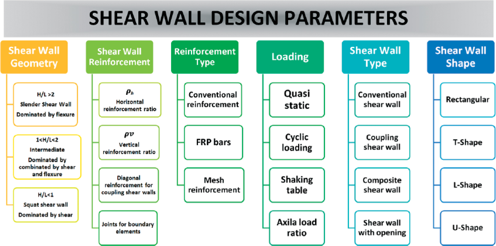
Figure 24.
Scheme for design parameters of shear walls
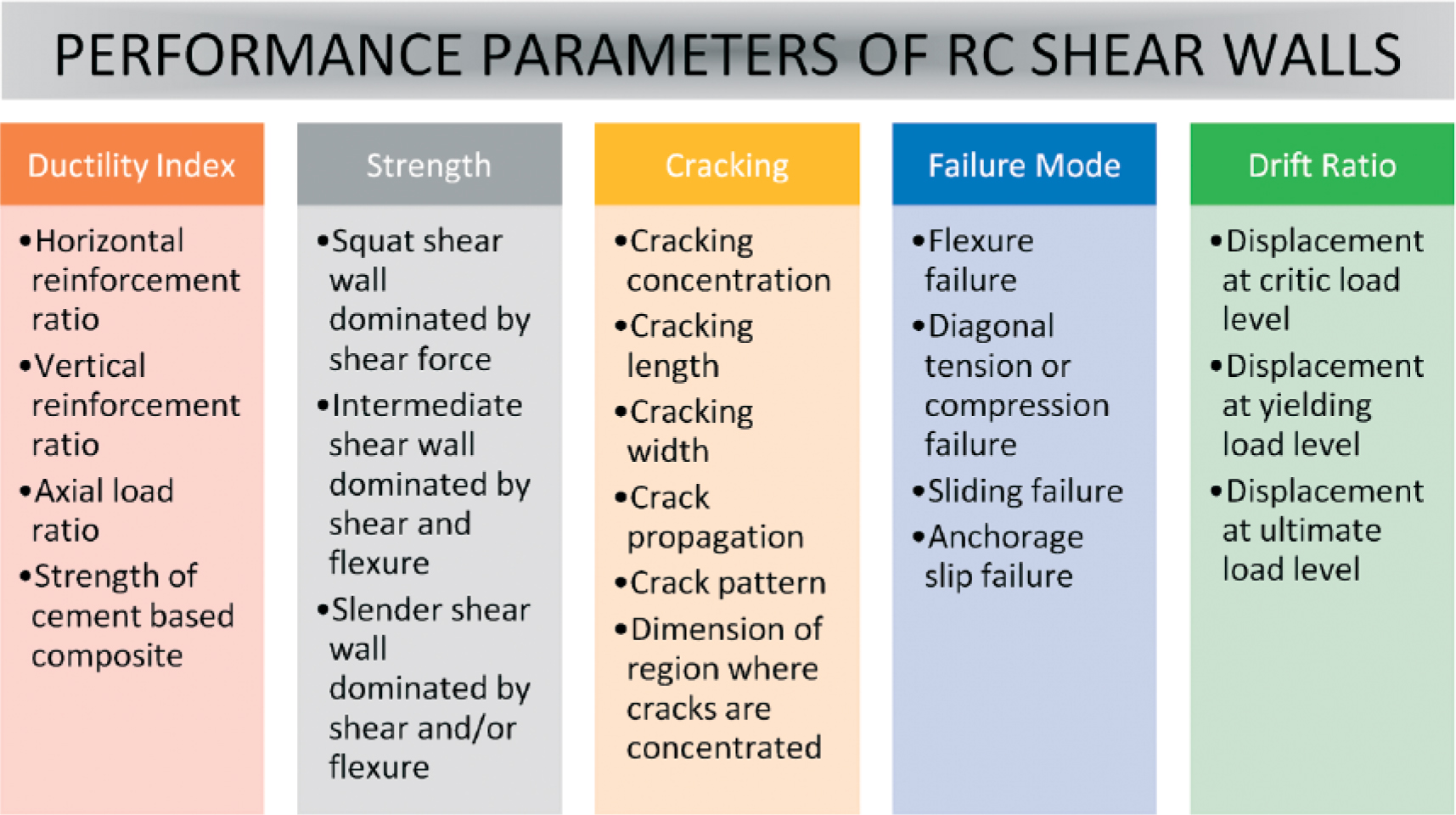
Figure 25.
Scheme of performance parameters of shear walls