
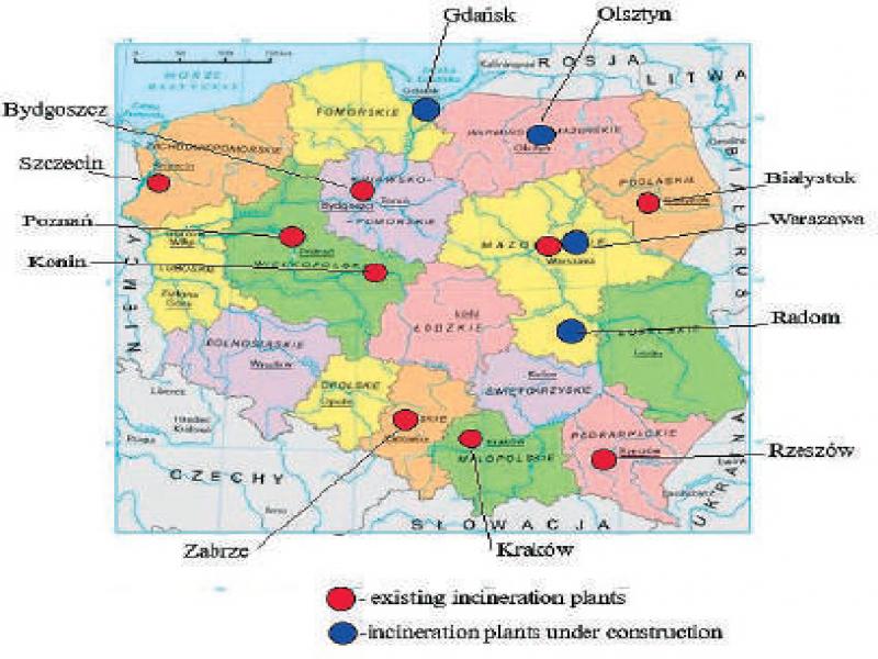
Figure 1.
Location of TPOK plants in Poland [2]
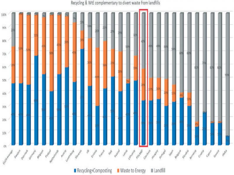
Figure 2.
Waste management methods in EU in 2019 [5]
Table 1.
Comparison of the CFB, BFB and Grate boiler technologies
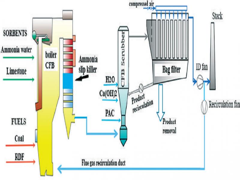
Figure 3.
Graphic diagram of the CFB boiler system in connection with the FGT installation
Table 2.
Characteristics of coal
| Parameters | Unit | Standardized limits |
| Lower calorific value | MJ/kg | 19-26 |
| Carbon | % | 58-78 |
| Hydrogen | % | 3-4.5 |
| Nitrogen | % | 1-2.6 |
| Sulphur | % | 0.4-1.4 |
| Chlorine | % | 0.1-0.4 |
| Oxygen | % | 5.5-8 |
| Volatile matter | % | 28-38 |
| Humidity | % | <10 |
| Bulk density | kg/m3 | 750-1000 |
| (Na+K) | % | <0.35 |
| Sb | mg/kg | <5 |
| As | mg/kg | <35 |
| Cd | mg/kg | <4 |
| Cr | mg/kg | <346 |
| Co | mg/kg | <55 |
| Cu | mg/kg | <225 |
| Pb | mg/kg | <182 |
| Ni | mg/kg | <227 |
| Sn | mg/kg | <67 |
| V | mg/kg | <333 |
| Hg | mg/kg | <0.2 |
| Zn | mg/kg | <262 |
Table 3.
Characteristics of RDF
| Parameters | Unit | Standardized limits |
| Lower calorific value | MJ/kg | 6-25 |
| Carbon | % | 35–40 |
| Hydrogen | % | 5-8 |
| Nitrogen | % | 0-1 |
| Oxygen | % | 25-30 |
| Sulphur | % | <0.5 |
| Chlorine | % | <1 |
| Ash content | % | <15 |
| Volatile matter | % | 50-80 |
| Humidity | % | <20 |
| Bulk density | kg/m3 | 100-300 |
| Sb | ppm | <20 |
| As | ppm | <10 |
| Cd | ppm | <5 |
| Cu | ppm | <150 |
| Pb | ppm | <100 |
| Cu | ppm | <150 |
| Pb | ppm | <100 |
| Ni | ppm | <50 |
| Hg | ppm | <1 |
Table 4.
Predicted based emissions
| Emission component – subject to reduction | Maximum baseline emissions | Unit |
| Dust | <30 * | g/Nm3 |
| SO2 | <2700 | mg/Nm3 |
| NOx | <210 | mg/Nm3 |
| HCl | <1100 | mg/Nm3 |
| HF | <65 | mg/Nm3 |
| Hg | <0.06 | mg/Nm3 |
| Cd+TI | <1.3 | mg/Nm3 |
| Sb+As+Pb+Cr+Co+Cu+Mn+Ni+V | <265 | mg/Nm3 |
Table 5.
Minimum emissions monitoring scope and monitoring frequency (BAT-AELs)
| Substance | Minimum monitoring frequency * |
| Dust | Continuous |
| SO2 | Continuous |
| NOx | Continuous |
| N20 | Once every year |
| CO | Continuous |
| TVOCCombustion plant total rated thermal input** | Continuous |
| HCL | Coal + RDF firing: continuous (WI) Coal firing: once every 3 months |
| HF | Coal + RDF firing: continuous (WI) Coal firing: once every 3 months |
| Metals and metalloids except mercury (As, Cd, Co, Cr, Cu, Mn, Ni, Pb, Sb, Se, Tl, V, Zn) | Coal + RDF firing – once every 6 months; Coal firing: once every year |
| Hg | Coal and/or Coal + RDF firing <300MWth (1) – once every 3 months Coal and/or Coal + RDF firing 300MWth (1) – continuous |
| Dioxins and furans (PCDD/PCDF) | Once every 6 months |
| NH3 | Continuous (when SNCR used) |
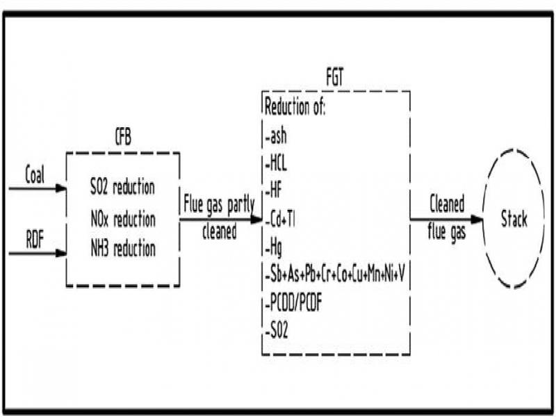
Figure 4.
Division of the CFB + FGT system emission control range for the co-firing coal with RDF operating mode
Table 6.
Emission levels in case of coal firing (BAT-AELs)
| Pollutant | Yearly average emission limit | Unit | BAT no. |
| Ash | 5 | mg/Nm3@6%O2 | BAT 22 |
| SO2 | 200 (1) ;150 (2) ;75 (3) | mg/Nm3@6%O2 | BAT 21 |
| NOx | 150 (1) ;100 (2) ;85 (3) | mg/Nm3@6%O2 | BAT 20 |
| CO | 140 (4) ;100(5) | mg/Nm3@6%O2 | BAT 20 |
| NH3 | 10 (7) | mg/Nm3@6%O2 | BAT 7 |
| HCL | 6 (1) ; 3 (6) | mg/Nm3@6%O2 | BAT 21 |
| HF | 3 (1) 2 (6) | mg/Nm3@6%O2 | BAT 21 |
| Hg | 3 (4) ; 2 (5) | Hg/Nm3@6%O2 | BAT 23 |
Table 7.
Emission levels in case for coal and RDF co-firing
| Pollutant | Yearly average emission limit | Unit | BAT no. |
| Ash | 5 | mg/Nm3@6%02 | BAT 68 |
| S02 | 200 (1) ;150 (2) ;75 (3) | mg/Nm3@6%02 | BAT 66 |
| N0X | 150 (1) ;100 (2) ;85 (3) | mg/Nm3@6%02 | BAT 64 |
| CO | 140 (4) ;100 (5) | mg/Nm3@6%02 | BAT 64 |
| NH3 | 10 (7) | mg/Nm3@6%02 | BAT 7 |
| HCL | 6 (1) ;3 (6) | mg/Nm3@6%02 | BAT 66 |
| HF | 3 (1) , 2 (6) | mg/Nm3@6%02 | BAT 66 |
| Hg | 3 (4) ;2 (5) | Hg/Nm3@6%02 | BAT 70 |
| Cd+TI | 12 (4) ;6 (5) | Hg/Nm3@6%02 | BAT 68 |
| TVOC | 5 | mg/Nm3@6%02 | BAT 71 |
| PCDD/PCDF | 0.03 | ng I-TEQ/Nm3@6%02 | BAT 71 |
| Sb+As+Pb+Cr+Co+Cu+Mn+Ni+V | 0.5 (4) ;0.2 (5) | mg/Nm3@6%02 | BAT 68 |
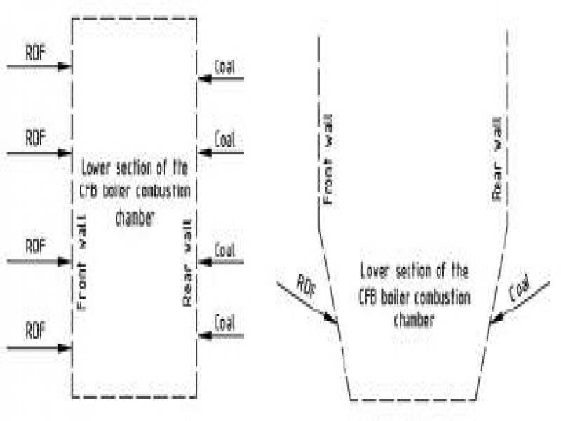
Figure 5.
Scheme of the fuel feeding to the combustion chamber of a CFB boiler
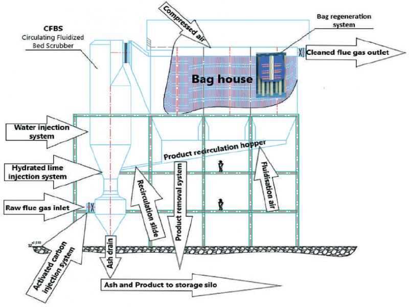
Figure 6.
Main components of the FGT semi-dry flue gas treatment system
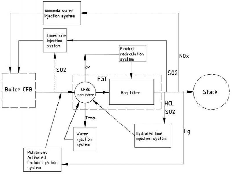
Figure 7.
Diagram of the emission control systems in CFB+FGT installation