
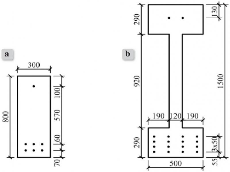
Figure 1.
Cross-sections of pretensioned concrete members: a) a rectangular beam, b) an I-shaped beam
Table 1.
Parameters of the analysed members
| The rectangular beam | The I-shaped beam | |
| The span L (m) | 15 | 21 |
| The load q (kN/m) | 9 | 25 |
| The perimeter of the member in contact with the atmosphere (m) | 2.2 | 4.76 |
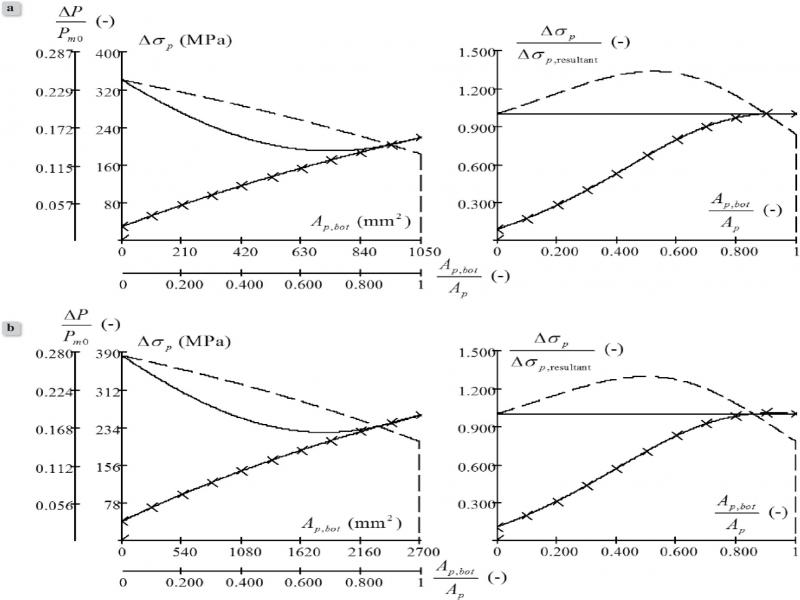
Figure 2.
Influence of the area of the cross-sections of the bottom tendons Ap,bot on the variations of stress in the top tendons (the dashed line), the bottom tendons (the continuous line with crosses), and the resultant tendon (the continuous line) for: a) the rectangular beam, b) the I-shaped beam.
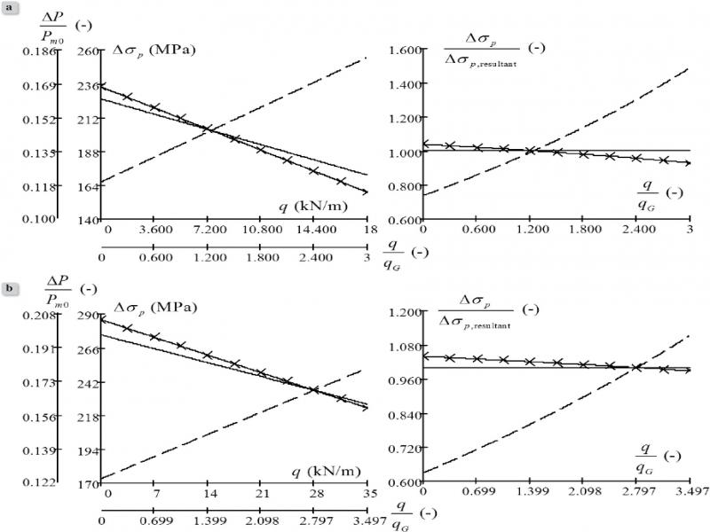
Figure 3.
Influence of the quasi-permanent load q on the variations of stress in the top tendons (the dashed line), the bottom tendons (the continuous line with crosses), and the resultant tendon (the continuous line) for: a) the rectangular beam, b) the I-shaped beam. qG is the member weight.
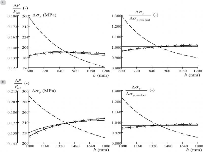
Figure 4.
Influence of the depth of the concrete cross-section h on the variations of stress in the top tendons (the dashed line), the bottom tendons (the continuous line with crosses), and the resultant tendon (the continuous line) for: a) the rectangular beam, b) the I-shaped beam