
Figure 1.
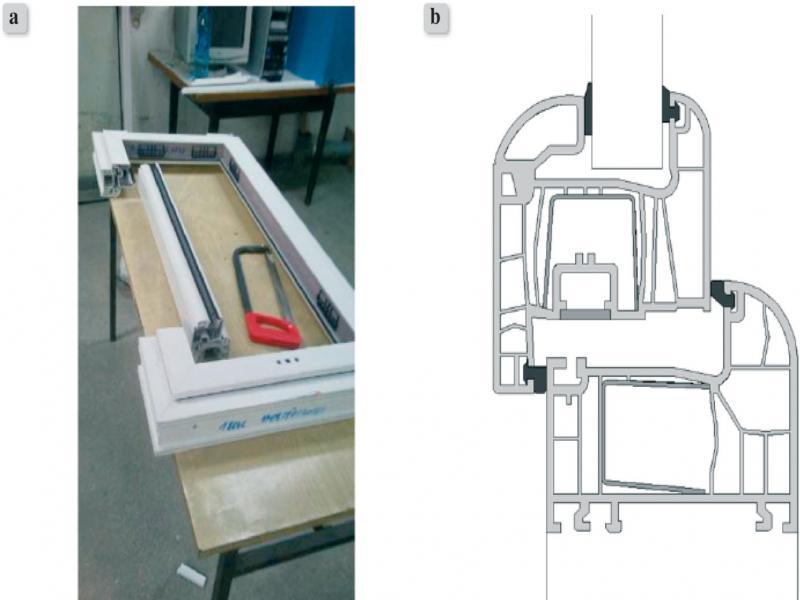
Figure 2.
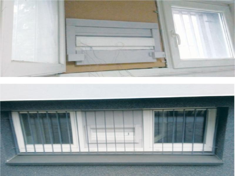
Figure 3.
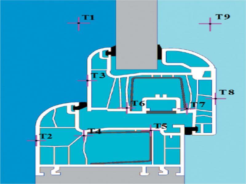
Figure 4.
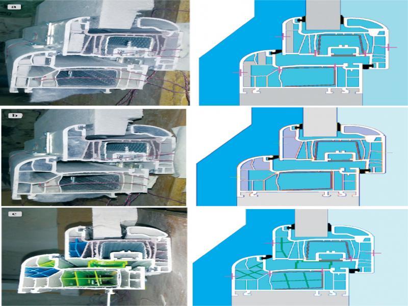
Figure 5.
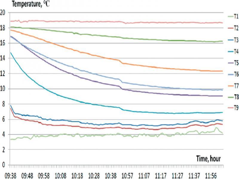
Figure 6.
Figure 7.
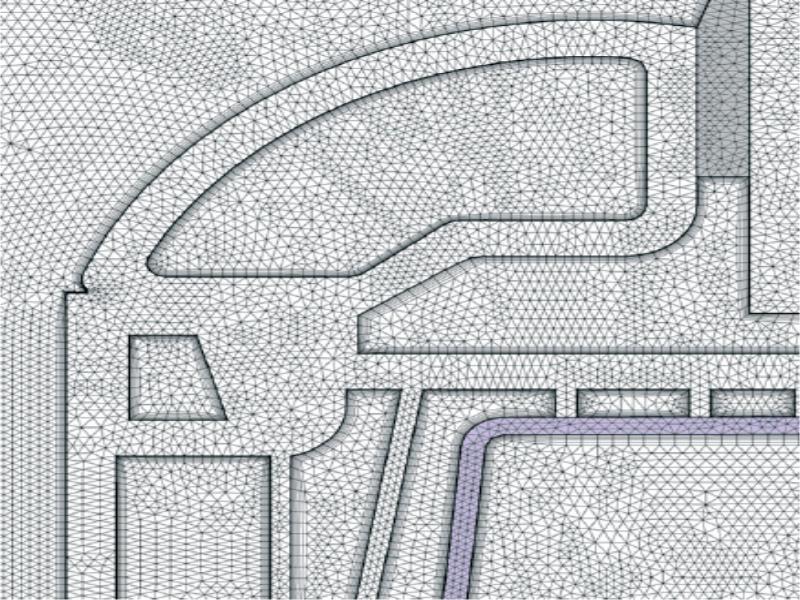
Figure 8.
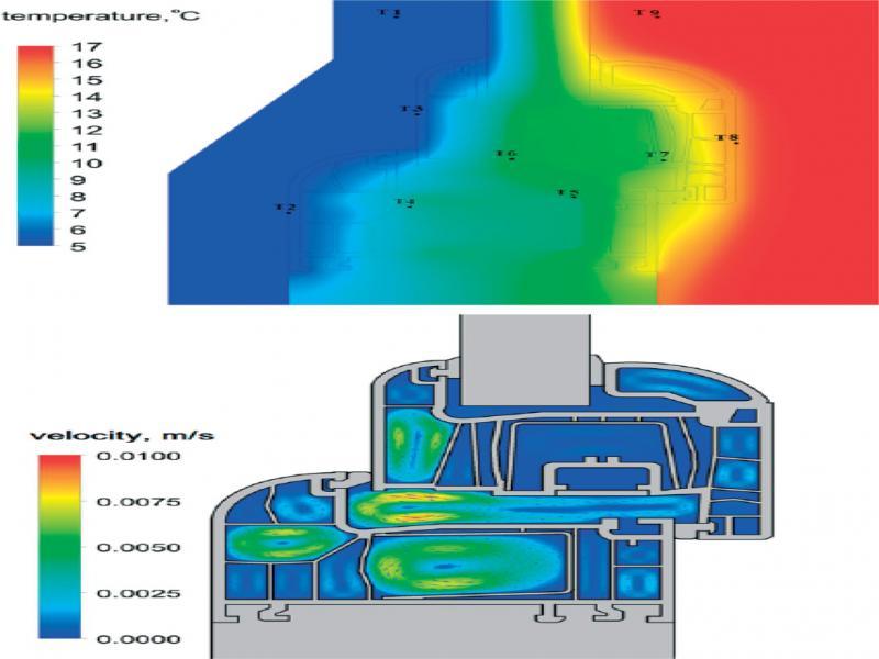
Figure 9.
The results of the measurements
| Temperature of thermocouple, °C | |||||||||
|---|---|---|---|---|---|---|---|---|---|
| Variant | T1 (outside air) | T2 | T3 | T4 | T5 | T6 | T7 | T8 | T9 (inter nal air) |
| 1. unmodified frame | 4.2 | 5.4 | 5.8 | 6.9 | 9.1 | 9.9 | 12.3 | 16.2 | 18.7 |
| 2. PIR insulation | 7.5 | 8.4 | 8.8 | 9.8 | 11.1 | 11.8 | 13.5 | 16.4 | 18.3 |
| 3. aerogel insulation | 5.0 | 5.4 | 5.7 | 7.5 | 9.6 | 10.5 | 12.5 | 16.2 | 17.6 |
| 4. 3D printed elements | 9.5 | 10.2 | 10.6 | 11.2 | 13.1 | 13.8 | 15.2 | 17.1 | 18.4 |
Thermal conductivity of materials used in the numerical model [11, 12, 13]
| Material | Thermal conductivity, W/(m•K) |
|---|---|
| PVC | 0.17 |
| Rubber | 0.24 |
| Steel | 50.0 |
| PIR board | 0.023 |
| Aerogel mat | 0.014 |
Comparison of measurements and simulations results for the experimental conditions
| Point number | Temperature from simulations, °C | Temperature from measurements, °C | Difference between measurements and simulation, °C |
|---|---|---|---|
| Unmodified profile | |||
| 2 | 5.3 | 5.4 | 0.15 |
| 3 | 5.4 | 5.8 | 0.4 |
| 4 | 8.3 | 6.9 | -1.381 |
| 5 | 10.7 | 9.1 | -1.61 |
| 6 | 11.4 | 9.9 | -1.53 |
| 7 | 12.5 | 12.3 | -0.21 |
| 8 | 15.7 | 16.2 | 0.49 |
| PIR board | |||
| 2 | 7.8 | 8.4 | 0.6 |
| 3 | 7.9 | 8.8 | 0.9 |
| 4 | 11.4 | 9.8 | -1.6 |
| 5 | 12.5 | 11.1 | -1.4 |
| 6 | 13.3 | 11.8 | -1.5 |
| 7 | 14.1 | 13.5 | -0.6 |
| 8 | 16.9 | 16.4 | -0.5 |
| Aerogel mat | |||
| 2 | 5.4 | 5.4 | 0 |
| 3 | 5.4 | 5.7 | 0.3 |
| 4 | 10.0 | 7.5 | -2.5 |
| 5 | 11.3 | 9.6 | -1.7 |
| 6 | 12.2 | 10.2 | -2 |
| 7 | 13.1 | 12.5 | -0.6 |
| 8 | 16.2 | 16.2 | 0 |
| 3D printedelements | |||
| 2 | 9.8 | 10.2 | 0.4 |
| 3 | 9.9 | 10.6 | 0.7 |
| 4 | 12.7 | 11.2 | -1.5 |
| 5 | 13.8 | 13.1 | -0.7 |
| 6 | 14.3 | 13.8 | -0.5 |
| 7 | 15.0 | 15.2 | 0.2 |
| 8 | 17.3 | 17.1 | -0.2 |
Heat flux and thermal transmittance of the profile for all the tested variants
| Additional insulation type | Heat flux per unit profile lenght with temperature difference 40K, W/m | Linear (per meter length of profile) thermal transmittance, W/(m•K) | Heat flux difference compared to the unmodified frame |
|---|---|---|---|
| none | 5.405 | 0.1351 | 0.00% |
| PIR board | 5.034 | 0.1258 | -6.85% |
| aerogel mat | 4.877 | 0.1219 | -9.76% |
| 3D printed elements | 5.173 | 0.1293 | -4.29% |
Discretization mesh parameters for different models
| Model number | Additional insulation type | elements | nodes |
|---|---|---|---|
| 1 | None | 592484 | 762270 |
| 2 | PIR board | 589848 | 760005 |
| 3 | Aerogel mat | 586312 | 757353 |
| 4 | 3D printed elements | 621424 | 782904 |