
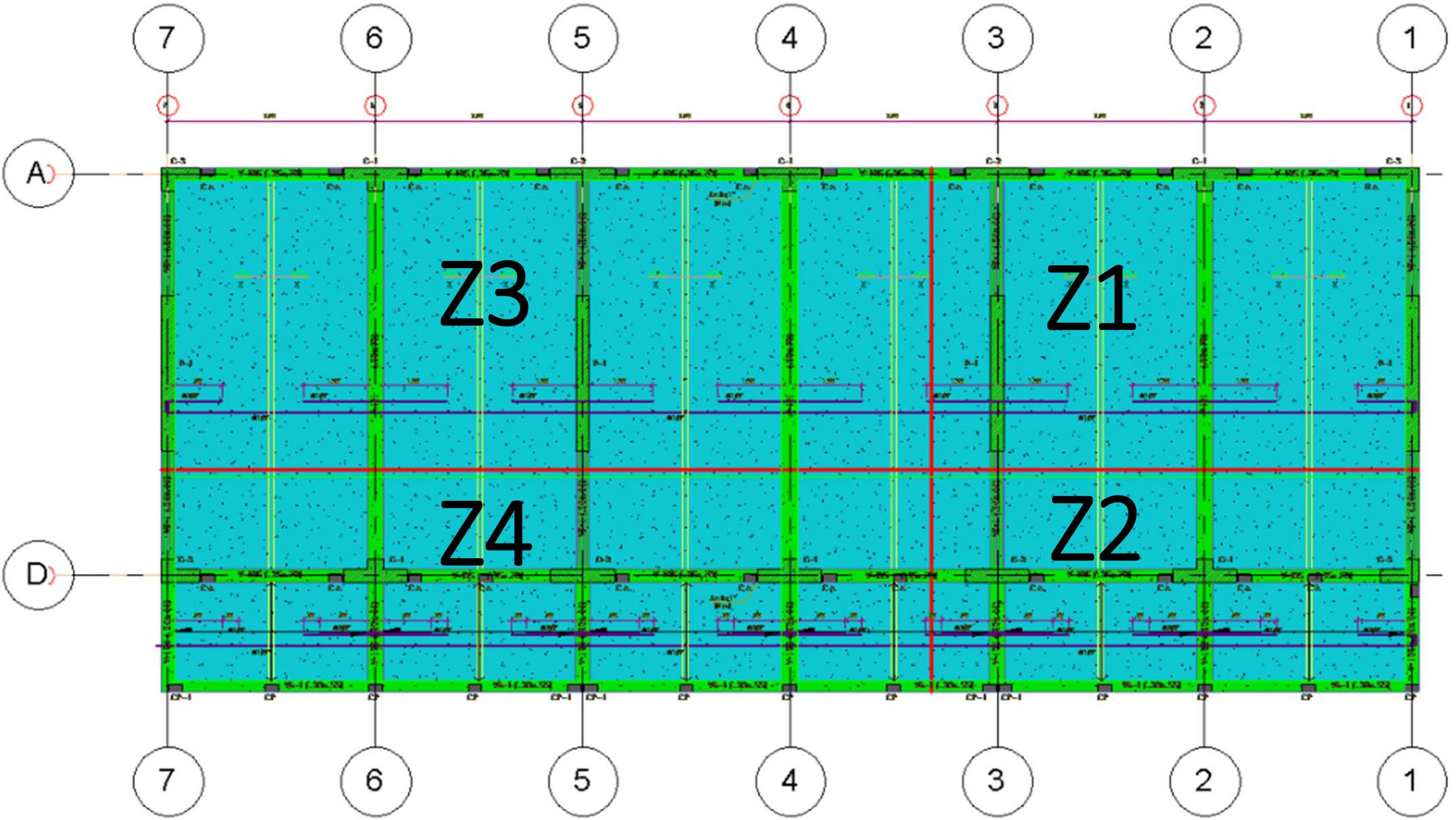
Fig. 1
Sectorization of structural works.
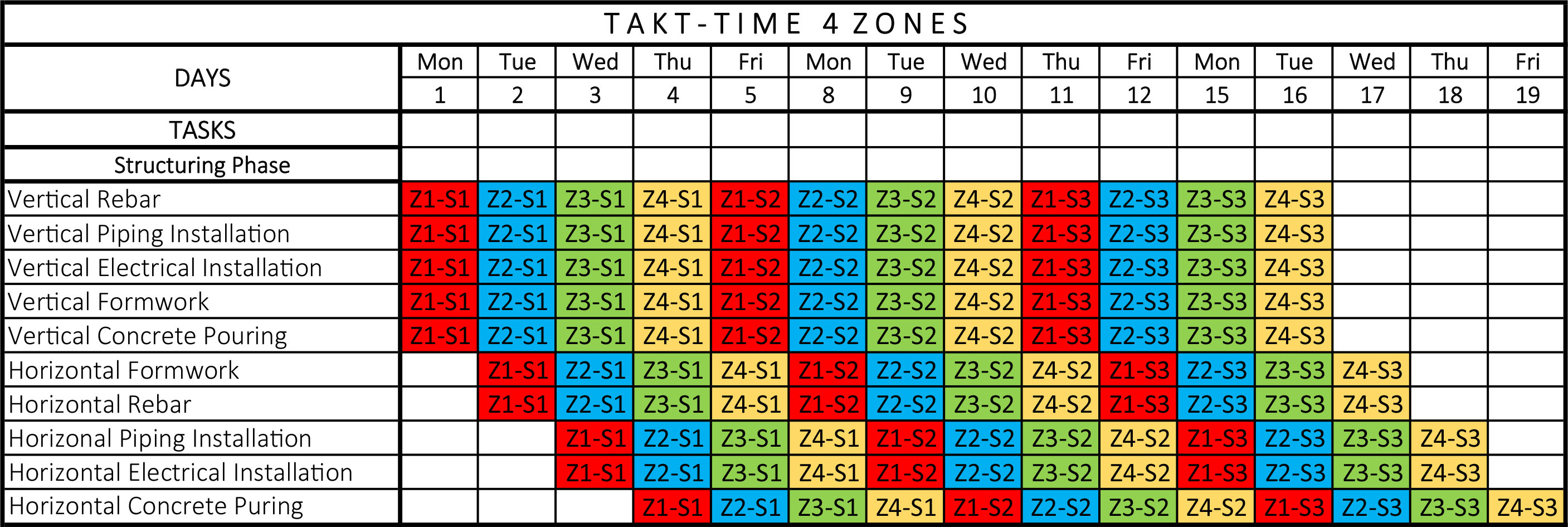
Fig. 2
Takt-time schedule of structural work. Z1 (Zone 1)–S1 (Story 1).
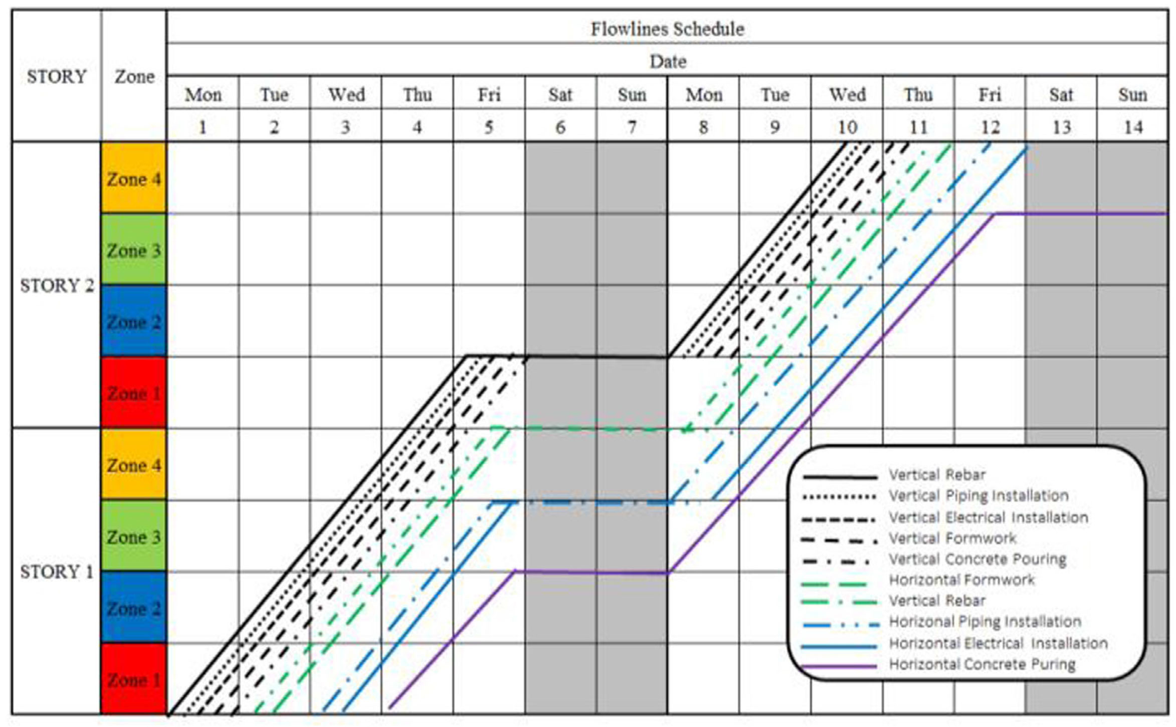
Fig. 3
Flowline schedule of the project.

Fig. 4
Principle of precedence diagram method.
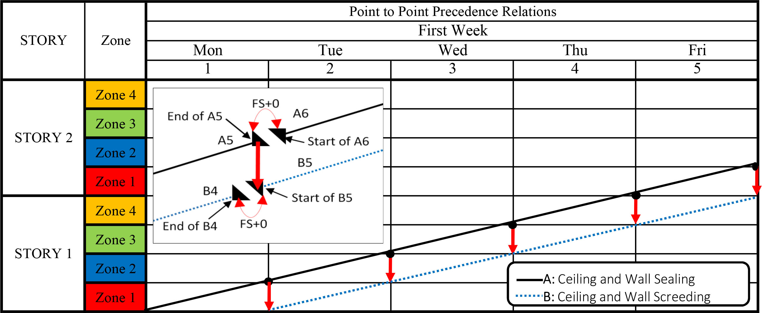
Fig. 5
Finishing activities using fragmentation and FS0 relationships (adapted from the study by Hajdu (2015)).
Tab. 1
Set of construction alternatives to be used in the three workshops.
| Alternative | Zones per story | Takt-time (day) | Footprint | Days per story | |||
|---|---|---|---|---|---|---|---|
| Z1 (m2) | Z2 (m2) | Z3 (m2) | Z4 (m2) | ||||
| 3A | 3 | 1 | 53 | 36 | 107 | — | 3 |
| 3B | 3 | 1 | 90 | 80 | 67 | — | 3 |
| 4A | 4 | 1 | 53 | 39 | 84 | 62 | 4 |
| 4B | 4 | 1 | 76 | 55 | 62 | 45 | 4 |
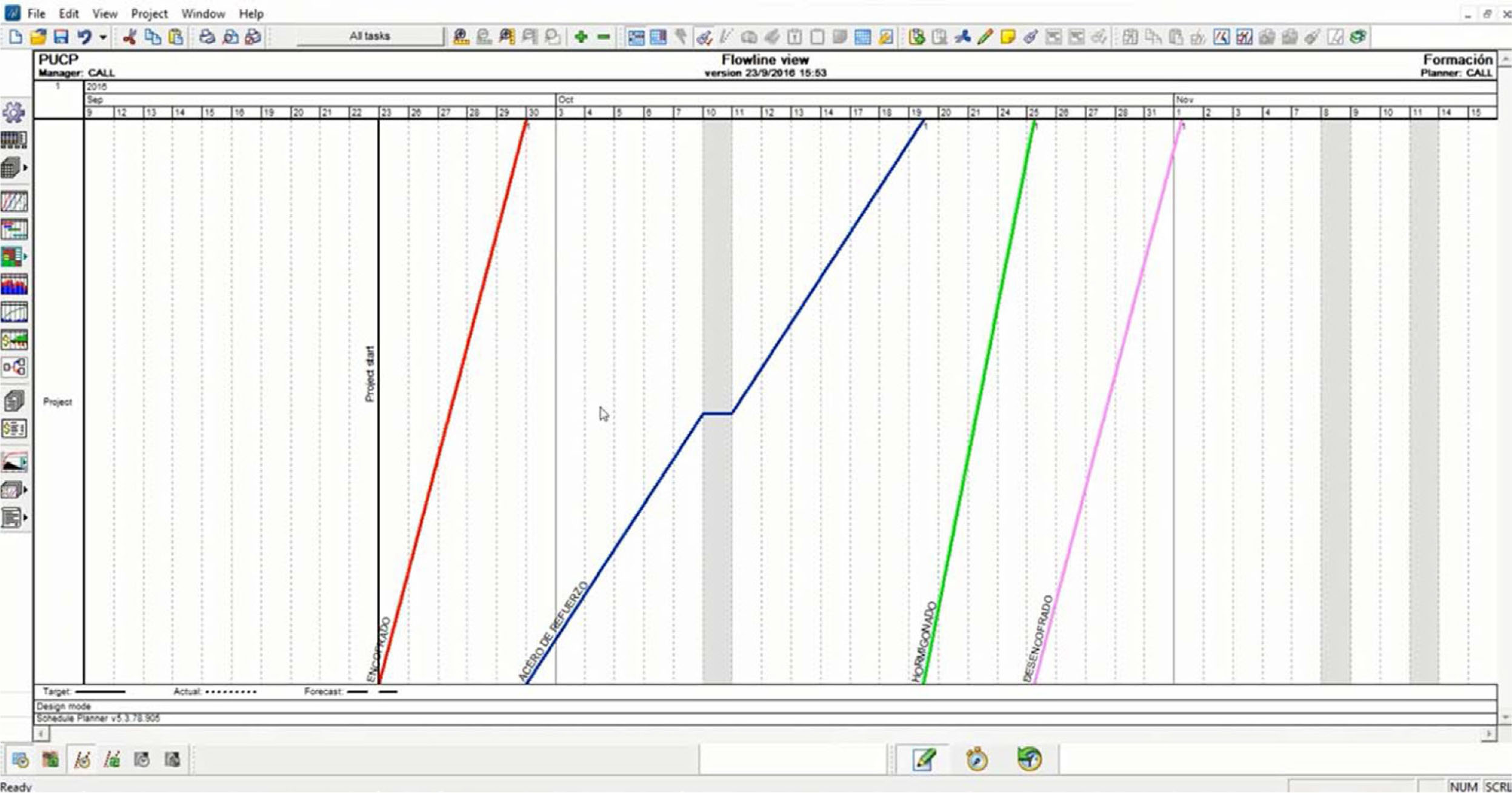
Fig. 6
Flowlines scheduling in Vico Office.
Tab. 2
Summary of the workshop design.
| Scheduling methods | Tools | Tasks | |
|---|---|---|---|
| Stage 1 | Takt-time, flowlines, and PTPPR | 2D drawings and Excel spreadsheets | Manual quantity takeoff |
| Manual design of crews | |||
| Use of Excel spreadsheets to create schedules | |||
| Simulation of planned vs. mock-up actual execution | |||
| Stage 2 | Takt-time, flowlines | 3D models, 4D models, Revit, and Navisworks 2016 | Automatic extraction of quantitative takeoff |
| Visualize 4D models | |||
| Detect process clashes in the 4D model | |||
| Comparison with Stage 1 | |||
| Stage 3 | Takt-time, flowlines | 3D models, 4D and 5D models, and Vico Office | Visualize 4D and 5D models |
| Automatic creation of schedules in Vico Office | |||
| Iteration of different crews changing data in 5D models | |||
| Comparison with Stages 1 and 2 |
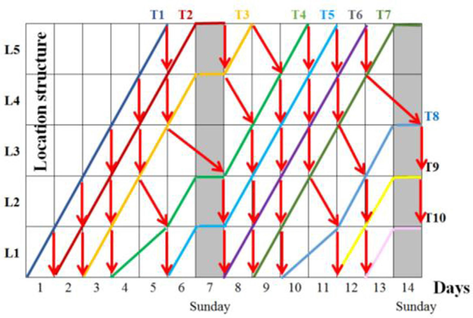
Fig. 7
Flowlines and point-to-point precedence relations (adapted from the study by Brioso et al. (2016)).
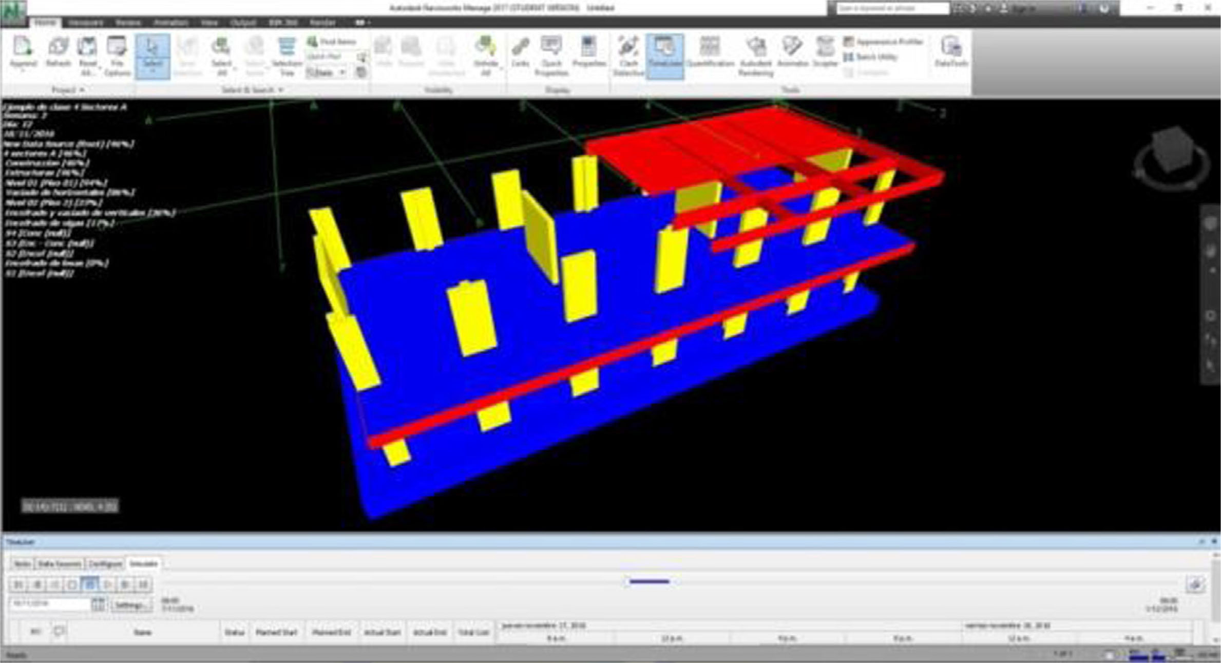
Fig. 8
4D model of one alternative in Navisworks.
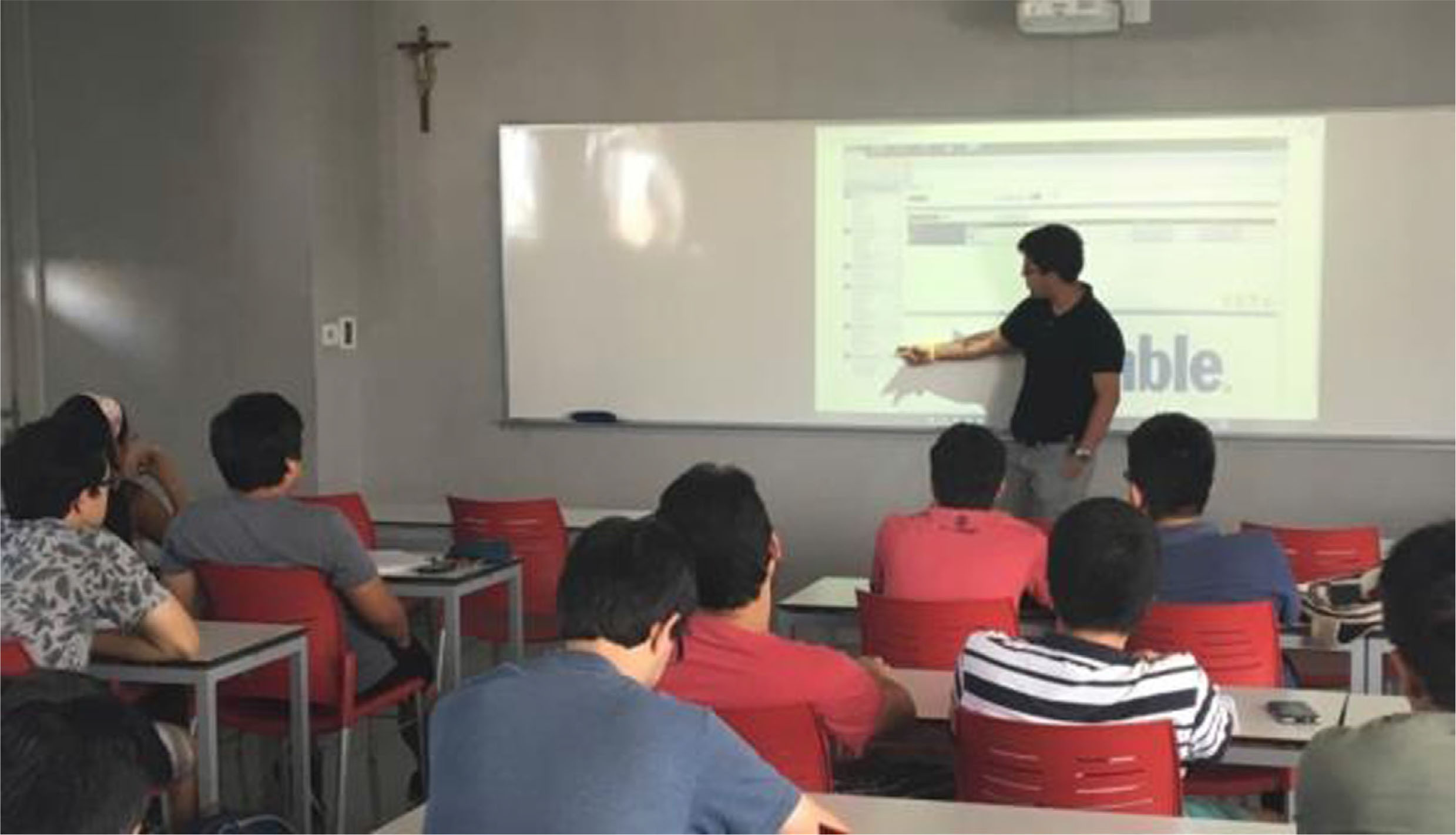
Fig. 9
Explanation of the workshop 3 with Vico Office.

Fig. 10
Generation of flowlines.
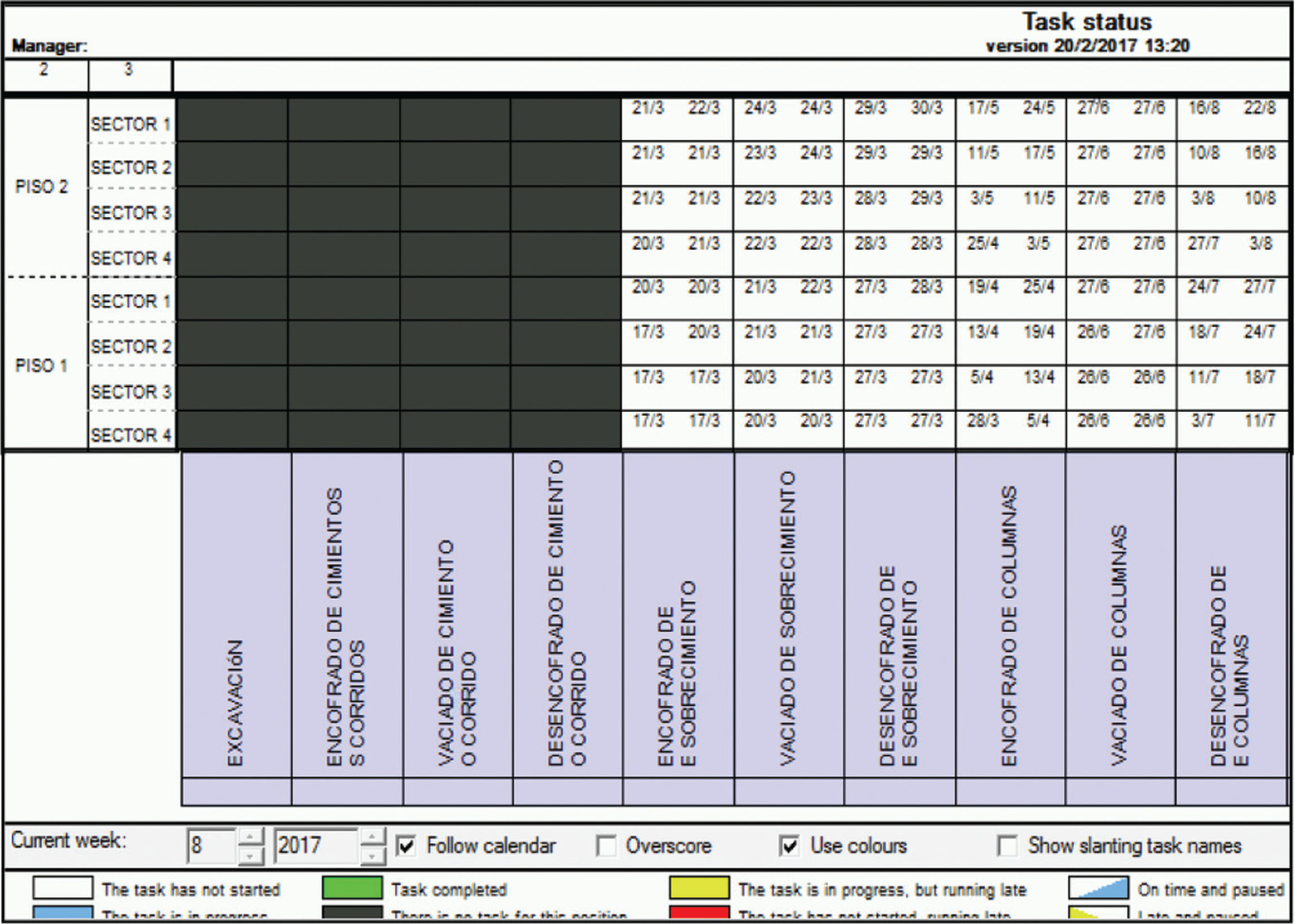
Fig. 11
Takt-time in Vico Office.
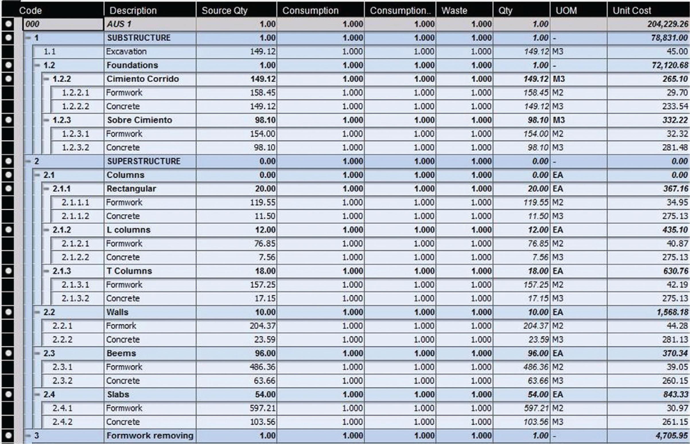
Fig. 12
Costs of the 5D model developed in Vico Office.
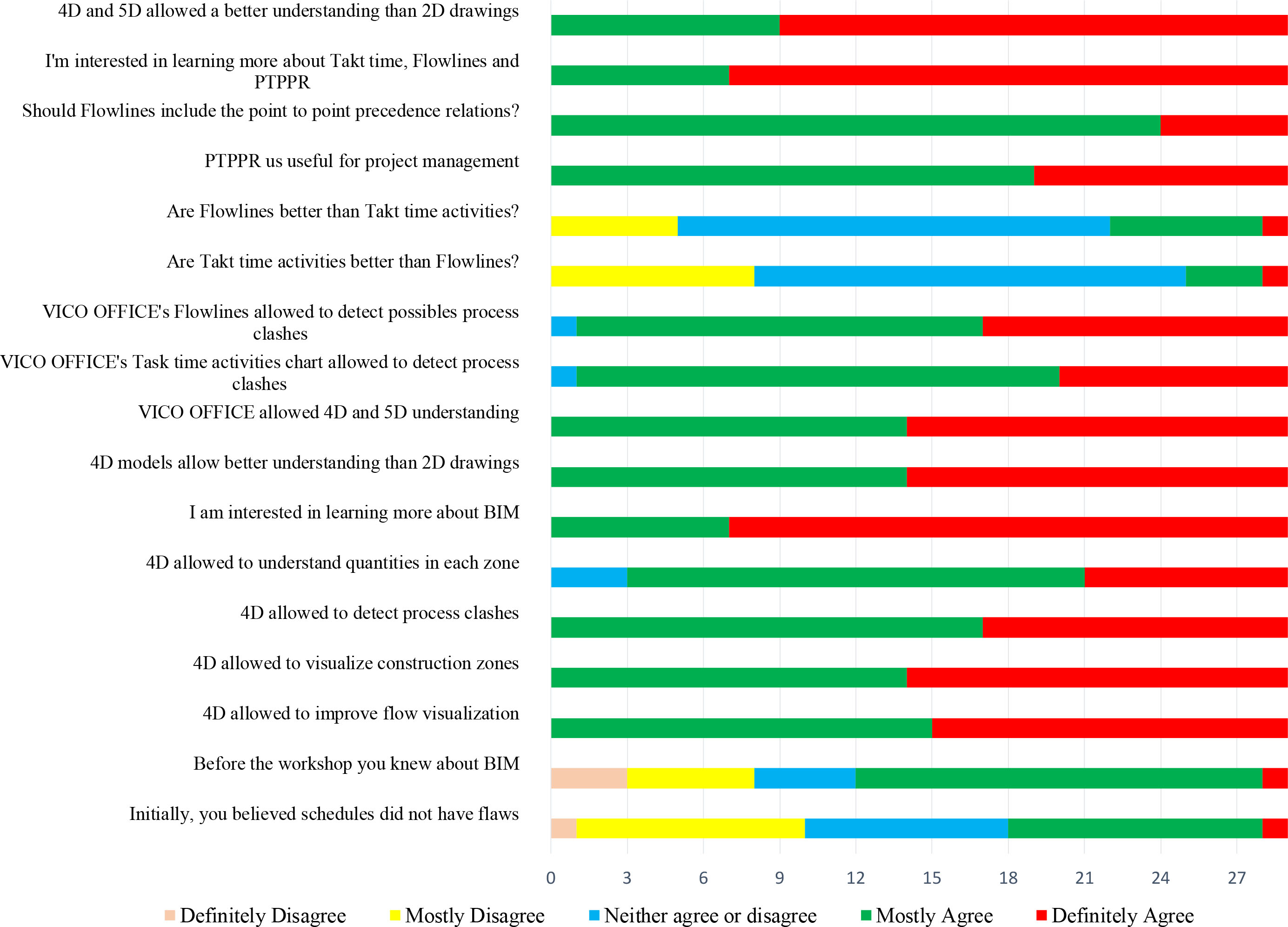
Fig. 13
Survey responses outline.