
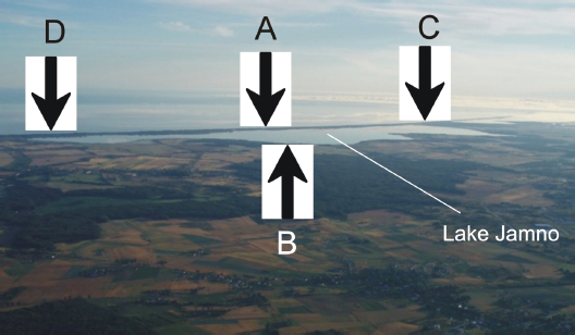
Figure 1
Location of automatic monitoring sites: A – Jamno Canal, B – Koszałek site, C – Łabusz site, D – Mielno site
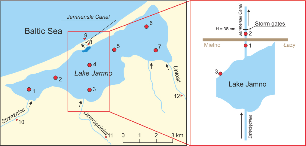
Figure 2
Location of gauging sites on Lake Jamno and the Jamno Canal (Cieśliński 2004) and location of water sampling sites used in the period 2013–2015
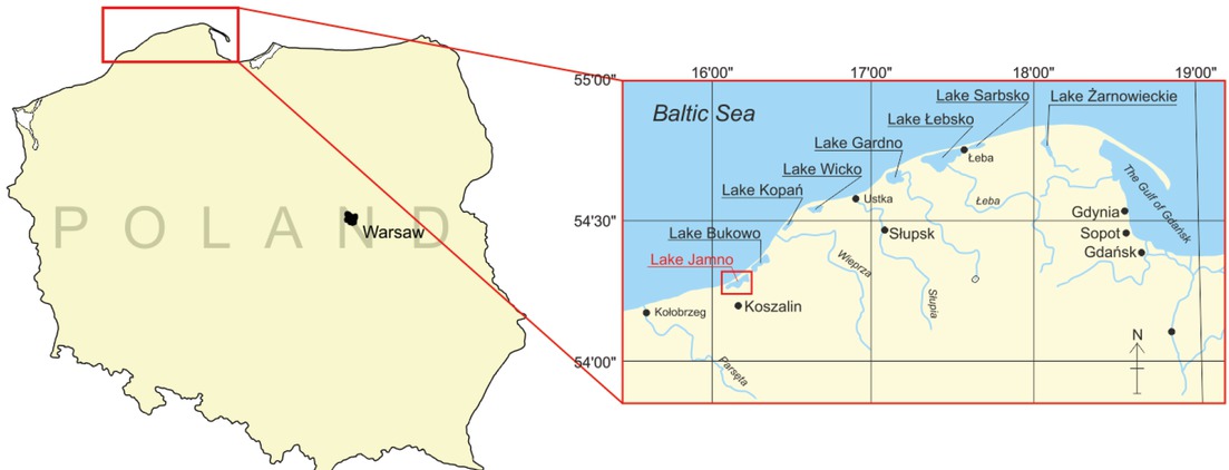
Figure 3
Location of Lake Jamno along the southern coast of the Baltic Sea with respect to other bodies of water in the area (Paturej 2006)
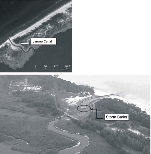
Figure 4
The Jamno Canal connecting Lake Jamno with the Baltic Sea – a bird’s eye view (https://www.google.pl)
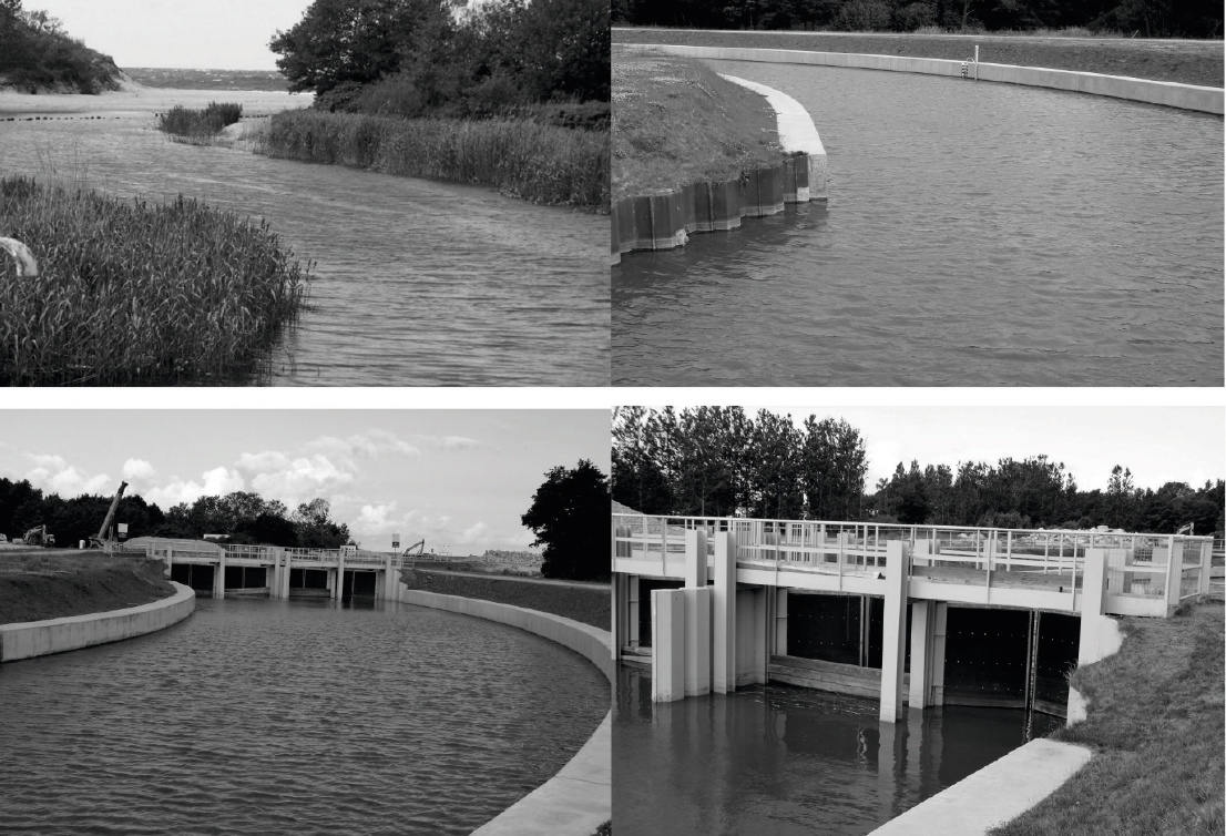
Figure 5
The Jamno Canal before and after the construction of the storm barrier along with a view of the storm barrier
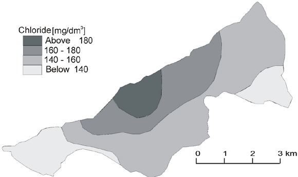
Figure 6
Distribution of chloride concentrations in the surface waters of Lake Jamno on 15 July 2002 (Cieśliński 2009a)
Table 1
Descriptive statistics for the chloride ion (mg l−1) and electric conductivity (μS cm−1) in water of Lake Jamno
| Indicator | Arithmetic average | Standard deviation | Maximum value | Minimum value | Coefficient of variation | |||||
|---|---|---|---|---|---|---|---|---|---|---|
| A | B | A | B | A | B | A | B | A | B | |
| Chloride | 297.8 | 173.2 | 162.8 | 99.1 | 698.0 | 477.0 | 133.0 | 70.0 | 54.7 | 57.2 |
| Conductivity | 1184.8 | 925.1 | 540.6 | 367.2 | 2870.0 | 2150.0 | 693.0 | 591.0 | 45.6 | 39.7 |
[i] A – point located opposite to the Jamnenski Canal, B – point located furthest from the Jamnenski Canal
Table 2
Descriptive statistics for the chloride ion (mg l−1) and electric conductivity (μS cm−1) in water of the Jamneński Canal
| Indicator | Arithmetic average | Maximum value | Minimum value | Coefficient of variation |
|---|---|---|---|---|
| Chloride | 457.0 | 925.0 | 44.0 | 77.8 |
| Conductivity | 1899.0 | 6995.0 | 855.0 | 60.0 |
Table 3
Average values of selected physical and chemical data obtained in the field in 2013–2015
| Site no. | Chloride (mg l−1) | Conductivity (μS cm−1) | Location of the measuring point |
|---|---|---|---|
| 1 | 44.0 | 404 | Jamno Canal (400 m from the shoreline of the lake) |
| 2 | 78.0 | 508 | Jamno Canal (600 m from the shoreline of the lake) |
| 3 | 38.0 | 394 | Lake Jamno (north–western part) |
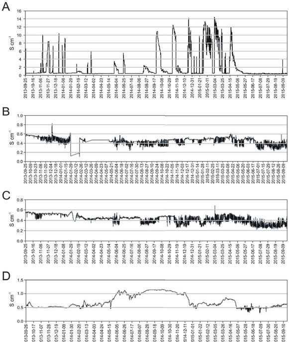
Figure 7
Specific conductivity (S cm−1) in the Jamno Canal (A), Lake Jamno (Koszałek site) (B), Lake Jamno (Łabusz site) (C) and Lake Jamno (Mielno site) (D) between 25 September 2013 and 20 September 2015
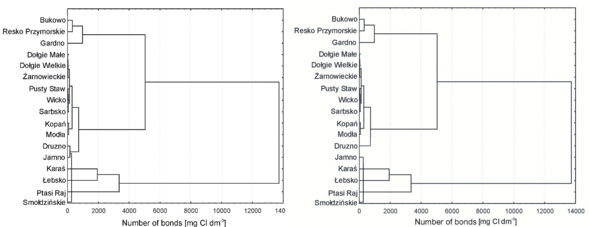
Figure 8
Lake classification tree diagram showing the minimum, maximum and mean chloride concentrations in selected coastal lakes before the construction of the gates on the Jamno Canal (figure on the left) and after their construction (figure on the right)
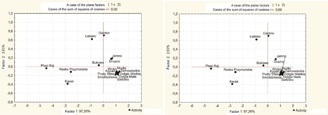
Figure 9
Classification of lakes using the method of principal components showing the minimum, maximum and mean chloride concentrations in selected lakes
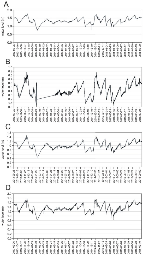
Figure 10
Changes in water levels (m) in the Jamno Canal, Lake Jamno (Koszałek site), Lake Jamno (Łabusz site) and Lake Jamno (Mielno site) between 25 September 2013 and 20 September 2015
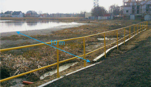
Figure 11
Recession of Lake Jamno’s shoreline after the construction of the storm barrier
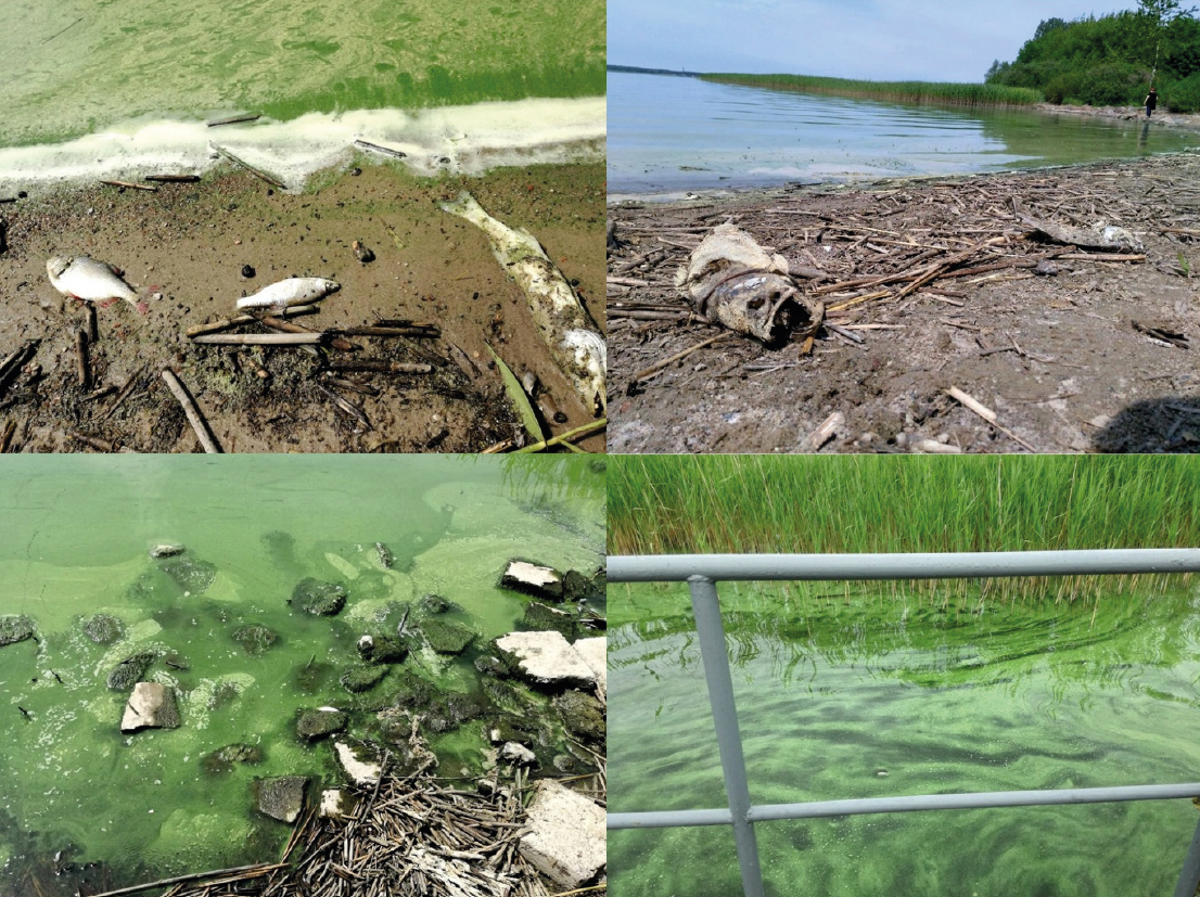
Figure 12
Blooms and fish kill in Lake Jamno (Author: Student Group of Koszalin University of Technology)