
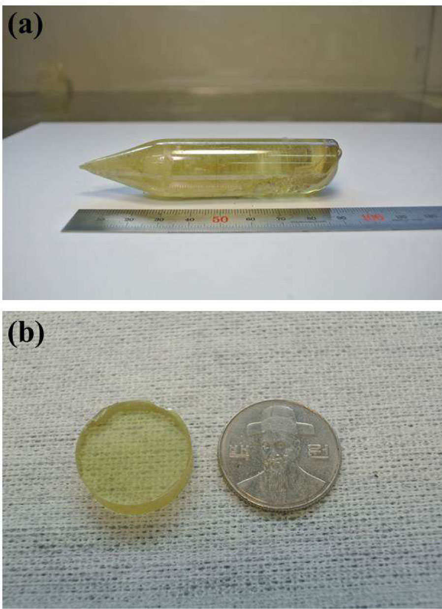
Fig. 1
(a) Single crystalline 1-inch TlBr ingot used in the study, (b) a diced and polished TlBr sample.
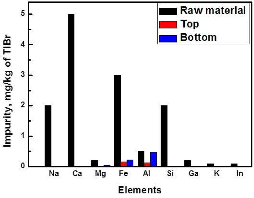
Fig. 2
ICP-MS results of the raw material, and top and bottom samples of TlBr.
Table 1
Summary of the major impurities observed in the raw material and in the three samples, which were measured using an ICP-MS.
| Unit [ppm] | Na | Ca | Mg | Fe | Al | Si | Ga | K | In |
|---|---|---|---|---|---|---|---|---|---|
| Raw material | 2.00 | 5.00 | 0.20 | 3.00 | 0.50 | 2.00 | 0.20 | 0.10 | 0.10 |
| Top | 0.00 | 0.00 | 0.01 | 0.15 | 0.12 | 0.00 | 0.00 | 0.00 | 0.00 |
| Middle | 0.00 | 0.00 | 0.00 | 0.04 | 0.09 | 0.00 | 0.00 | 0.00 | 0.00 |
| Bottom | 0.00 | 0.00 | 0.04 | 0.22 | 0.47 | 0.00 | 0.00 | 0.00 | 0.00 |
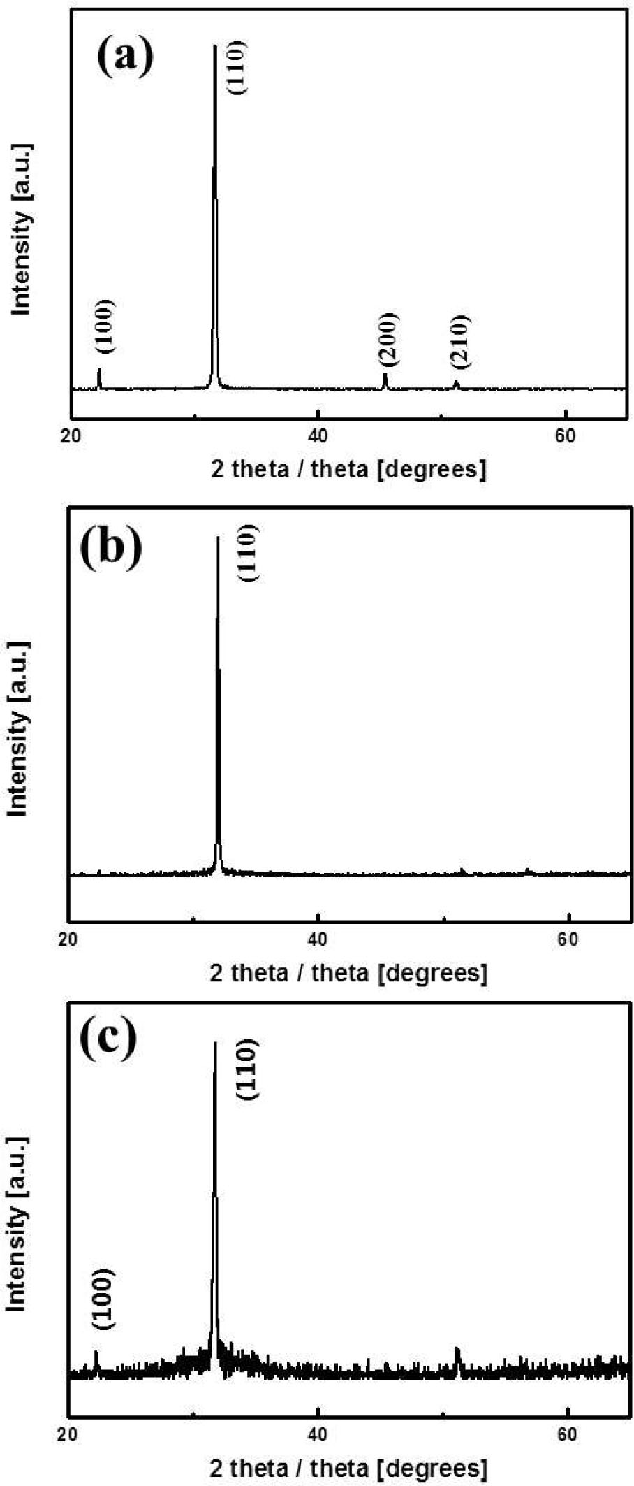
Fig. 3
XRD patterns for the top, middle, and bottom samples of TlBr.
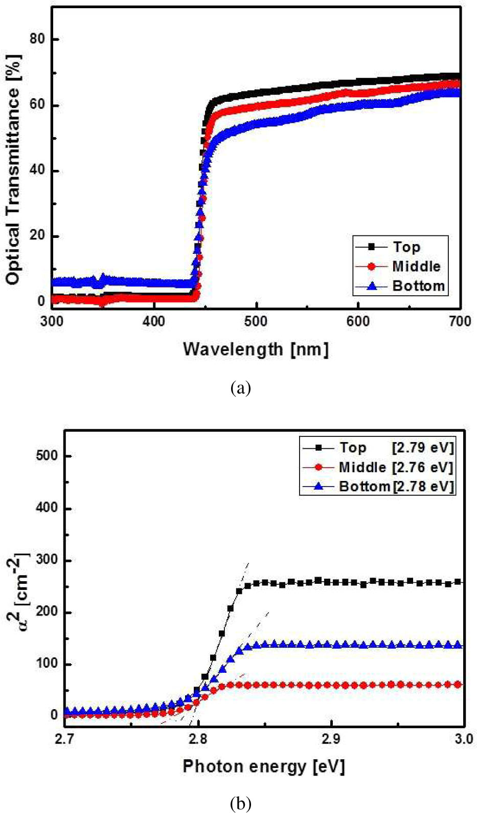
Fig. 4
(a) Transmittance and (b) α2 vs. hν curves for the top, middle, and bottom samples of TlBr.
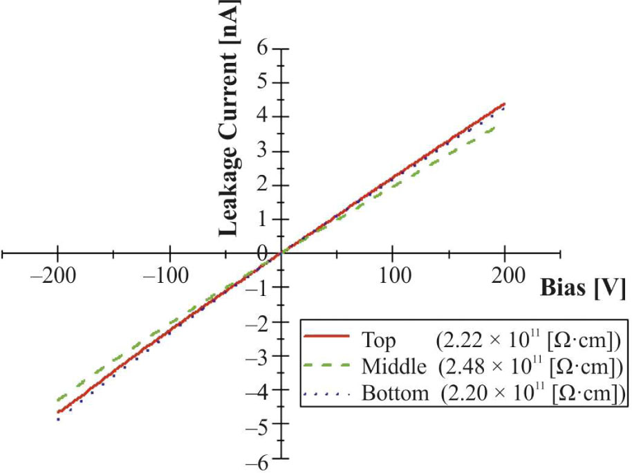
Fig. 5
I-V characteristics and resistivities of the top, middle, and bottom samples of TlBr.
Table 2
Summary of the Al impurity concentrations, FWHM (full width at half-maximum) values from the main peaks in the XRD graphs, optical bandgaps, and resistivities of the three samples used in this study.
| Top | Middle Bottom | ||
|---|---|---|---|
| Al impurity conc. [ppm] | 0.12 | 0.09 | 0.47 |
| FWHM [radian] | 0.215 | 0.156 | 0.223 |
| Optical bandgap [eV] | 2.79 | 2.76 | 2.78 |
| Resistivity [×1011 Ω·cm] | 2.2 | 2.5 | 2.2 |